Sw 2 380 di switching unit – REMKO PWW 5000 User Manual
Page 10
10
Design
◊ Rotary current 400 Volt, fan 2-speed, maximum
electrical capacity 4 kW
◊ On-plaster mount
◊ Full motor protection through integrated connections
for thermal contacts
◊ Plastic housing, protection type IP 65, protective in-
sulation in accordance with VDE
◊ Front plate with symbols for switching positions
◊ Power input and protective conductor terminals,
main contactor
◊ Control fuse, control switch with the functions “Off/
Speed 1/Speed 2”
◊ Operating light (goes out when there is a fan mal-
function and/or power interruption to the switching
unit)
◊ Reset button, motor output terminals, connection ter-
minals for thermal contacts and room thermostat.
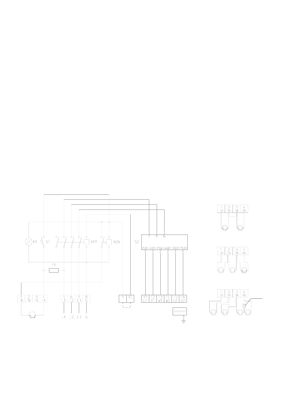
Wiring diagram
Thermal protection for
2 units
Thermal protection for
3 units
Thermal protection for
4 units
Connect additional
thermal
contacts in a row
Luster–
terminal
Thermal contact
Power switch
Room thermostat
or bridge
Fan motor
Group switching
The switching unit is suitable for group switching. Sev-
eral motors wired the same way can be connected to
one switching unit.
The total capacity of the connected motors may not ex-
ceed the permissible switch capacity of the switching
unit. The thermal contacts of all motors are to be con-
nected in a row.
See figure below.
SW 2 380 DI switching unit
Legend
Grounding and earthing or protective wiring and
fuse protection must be done
by the customer in
accordance with the requirements of the VDE as
well as the responsible EVU.
*
Switching on again after a problem
◊ Each time the power supply is interrupted or the fan
malfunctions, the fan reset button has to be pressed
once.
We reserve the right to make changes to dimensions and design in the interest of technical progress.
S1
Fan reset button
K2A Auxiliary
relay
F1 Control
fuse
S2 Control
switch
K1M Contactor to fan motor
H1 Operating
light
Star Delta Switch