Maintenance – REMKO PG 25 User Manual
Page 8
8
Maintenance
The units are to be checked by an expert as to their
perfect operation, when it is necessary and in accordan-
ce with the terms of use, but at least every two years.
The result of this check is to be recorded in a test certi-
ficate, which is to be kept safely until the next check is
carried out, and which can be presented to authorized
persons at any time.
The persons charged with the operation of the units
have to check these before starting the operation as to
visual faults at the control and safety devices, and they
have to make sure that the protective devices have be-
en fitted.
In the case of faults the supervisor is to be informed.
If those faults endanger the operational reliability of the
unit, its operation is to be stopped!
The units are to be maintained regularly, but at least
after each heating period to ensure their trouble-free
operation and a long service life.
The units are to be kept free from dust and other dirt,
and it is to be cleaned with a dry or humid cloth
(do not use water jets for cleaning).
Do not use any aggressive cleaning agents or
cleaners containing solvents.
The suction opening for combustion air, as well as
the injector fitted behind it and the gas nozzle are
to be checked regularly to ensure that they are free
from dirt.
Clean gas burner and gas nozzle regularly.
Clean diaphragm plate regularly.
The suction and blow off grid are to be checked
regularly to ensure that they are free from dirt,
otherwise they are to be cleaned.
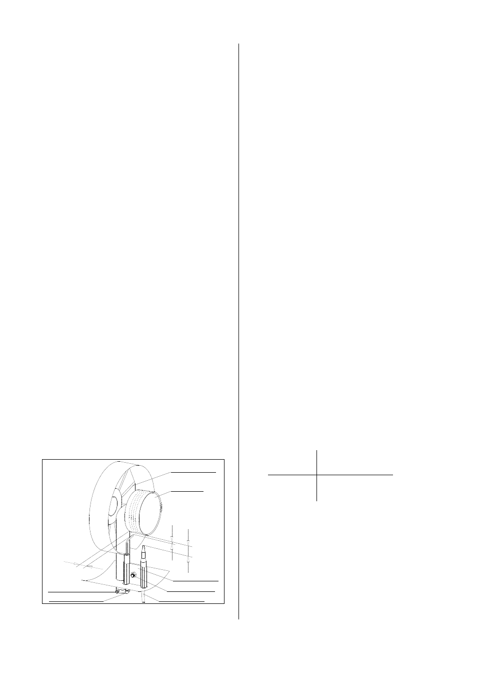
Removal and Cleaning of the Gas Burner
Remove blow-off protective grid and outside casing,
as well as the inspection cover at the lower side of
the unit.
Loosen clamping screw of the nozzle holding device.
Remove iginition cable from ignition electrode
(Take care of cap nut and lock washer).
Screw capillary tube off the safety pilot.
Release clamping screw of electrode holder and
remove ignition electrode and thermocouple.
Loosen 4 fastening screws of the burner and take
burner out of unit.
Clean burner using a steel brush and compressed
air and assemble in reverse order.
Set ignition electrode and thermocouple according to
the following instructions.
Assemble all the parts thoroughly in reverse order.
Control the functions of the complete unit and
carry out a tightness check for all gas-bearing
connections using soap solution and leakage
detection spray, respectively.
Intensive yellowish flames indicate that the
fresh air supply is probably insufficient and that
there is some dirt inside the unit, respectively.
Sizes in mm
Type A B C
PG 25 3 20 15
PG 50 3 35 15
The indicated sizes are based on
approximate values.
Setting Hints:
Size A = distance of ignition electrode to burner
Size B = position of thermocouple tip
Size C = position of ignition electrode tip
Make sure that the gas supply opening has
been closed and the mains plug has been
taken out of the mains socket before
carrying out any work regarding the unit.
Setting and maintenance is to be carried out
only by authorized experts!
diaphragm plate
gas burner
electrode holder
clamping screw
thermocouple
ignition electrode
clamping screw
A
B
C