Wiring diagram, Technical data, Service and guarantee – REMKO PGM 30 User Manual
Page 9
9
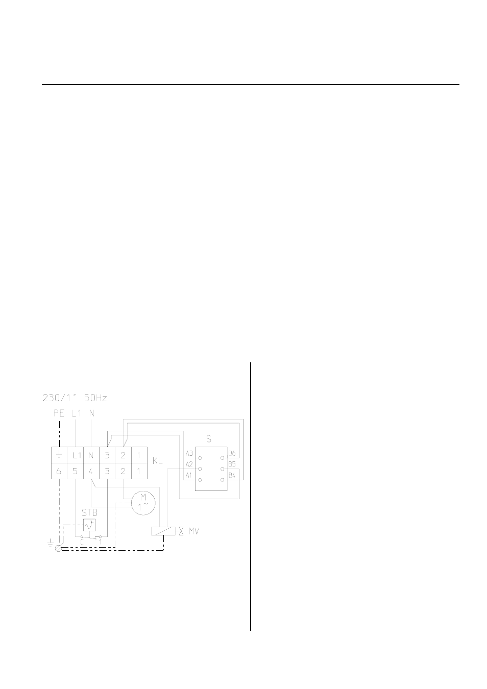
Wiring Diagram
MV = gas valve
M = fan motor
STB = safety temperature limiter
KL = terminal strip
S = operating switch
Technical Data
Series
PGM 30 / 30 E
PGM 60 / 60 E
Rated heat output
kW
26
55
Heating capacity
kW
adjustable from 10 to 26
adjustable from 25 to 55
Air output
m³/h
800
1,450
Fuel/type of gas
Liquid gas Cat. I
3 B/P
,
I
3+
Gas pressure
bar
1,5
1,5
Gas consumption
kg/h
0.78 - 2.0
1.95 - 4.27
Electrical connection 1~
V
230
230
Frequency
Hz
50
50
Power consumption max.
kW
0,07
0,11
Fuse protection
A
10
10
Type of protection
IP 44
IP 44
Sound pressure level L
pA
1m
1)
dB(A)
56 - 69
62 - 72
Weight (without accessories)
kg
12
20
Dimensions total
length
mm
450
650
width mm
260
320
height
mm
410
510
1) noise measuring DIN 45635 - 01- KL 3
Proper Use
These devices have been designed and equipped exclu-
sively to be used for heating and ventilation for industrial
and commercial purposes.
The manufacturer is not liable for any damage resulting
from non-adherence to manufacturer specifications, le-
gal requirements or any modifications to the units.
*
An operation/use other than indicated in these in-
structions is prohibited!
In the case of non-compliance, we assume no li-
ability and our guarantee becomes null and void.
Service and Guarantee
For the guarantee to be valid, the customer must com-
pletely fill out the “guarantee certificate” enclosed with
all heating units and send it back to REMKO GmbH &
Co. KG in a timely manner after purchasing of the unit
and putting it into operation.
The units have undergone testing at the factory to ensure
proper functioning. If there are still malfunctions that
cannot be fixed by the operator using the troubleshoot-
ing instructions, please contact your dealer or contract
partner.