Unit shut down, Maintenance – REMKO PGM 30 User Manual
Page 8
8
Unit Shut Down
1. Close all cylinder valves.
2. Let the flame burn out.
3. Set the operating switch to “0”.
Off.
4. Unplug the unit plug from the power
supply.
Maintenance
Depending on the operating conditions, the units must
be serviced as necessary, at least once every two years
by a authorised individual to ensure that they are func-
tioning properly
The test results must be recorded in a test log which is
kept in a safe place until the next test so that it can be
provided to authorised persons for control purposes at
any time.
Regular maintenance and care, especially after each
heating period, are required to ensure a long service life
and a faultless operation of the unit.
*
Adjustments or maintenance work may only be
performed by authorised personnel!
Please observe the following:
The unit must be maintained and cleaned at regular
intervals.
The unit must be kept free of dust and other deposits
and may only the cleaned using a dry or damp cloth.
Do not use place the unit in a direct stream of water.
Do not use any aggressive cleaning agents or those
which are harmful to the environment.
Do not use cleaning agents which contain solvents.
Use only suitable cleaners even when the unit is ex-
tremely dirty.
Check air suction and blow-out grille on a regular
basis and clean when necessary.
Make sure that the air intake for combustion air, the
injector behind it and the gas nozzle are not dirty.
Check gas burner, gas nozzle and gasket for dam-
age; replace when necessary.
Clean baffle plate regularly.
When the unit is being serviced, adjusted or re-
paired, the gas supply has to be turned off and the
unit unplugged from the power supply!
*
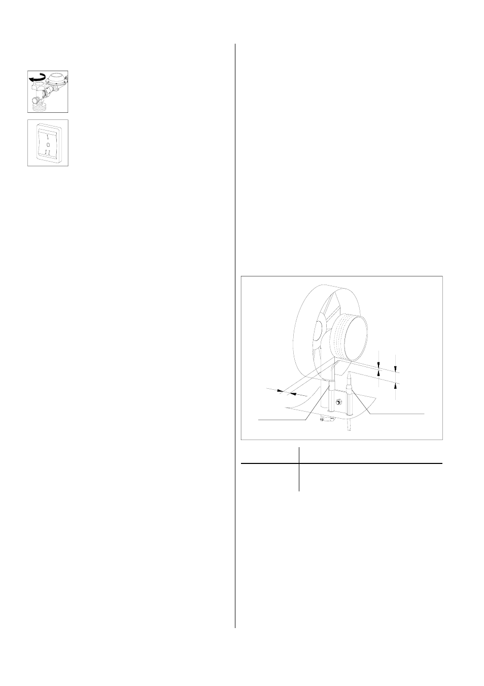
A
B
C
Ignition
electrode
Thermocouple
Removing and Cleaning the Gas Burner
1. Shut off the gas supply and unplug the unit from the
power supply.
2. Remove the blow-out grille and the outside casing.
3. Loosen the clamping screw on the nozzle holder.
4. Remove the ignition cable from the ignition elec-
trode.
Pay attention to the cap nut and the lock washer.
5. Screw the thermocouple capillary tube out of the
safety pilot.
6. Loosen the fastening screws on the burner and re-
move the burner with ignition electrode and thermo-
couple from the unit.
7. Clean the burner using a steel brush and com-
pressed air.
8. Put the burner with ignition electrode and thermo-
couple back into the unit.
9. If necessary, set the ignition electrode and thermo-
couple by following the instructions below.
10. Assemble all other parts in the reverse order.
11. Test the entire unit to ensure that it is functioning
properly; make sure that all gas supply hoses are
impermeable using either a soap solution or a leak
detection spray.
12. Conduct an electrical safety test after performing
any maintenance work.
Type
A
B
C
PGM 30 / 30E
3 mm
15 mm
20 mm
PGM 60 / 60E
3 mm
15 mm
35 mm
approx. dimensions
Bright yellow flames are an indication that the
fresh air supply is insufficient or that there is dirt
inside the unit.
*