Electrical wiring diagram – REMKO DZH 20-2 User Manual
Page 17
17
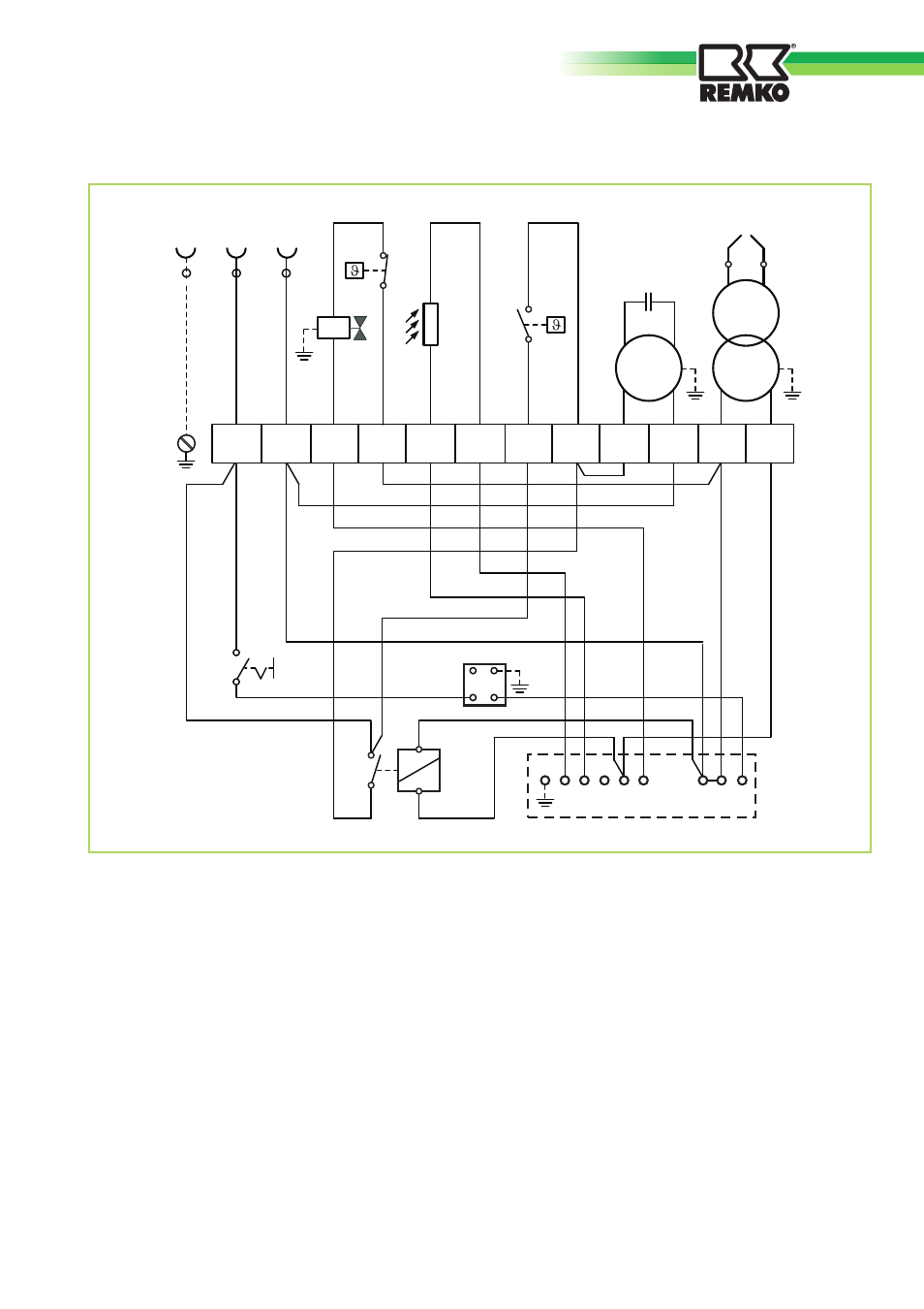
Electrical wiring diagram
We reserve the right to make changes in dimensions and design in the interest of technical advances.
Legend:
BS
= Operating switch
C
= Condenser
FZ
= Photoelecrtic cell
HS
= Auxiliary relay
M
= Motor
MV
= Solenoid valve
~
1 2 3 4 5 6 7 8 9 10 11 12
PE
L
N
230 V / 50 Hz
BS
RS
MV
FZ
ZE
ZT
M
C
2 3
RT
NK
STB
A1
A2
14
11
HS
1 2 3 4 5 6 7 8 N 9
NK
= Re-cooling thermostat
RS
= Relay socket
RT
= Thermostat plug socket
STB
= Safety limiter
ZE
= Ignition electrode
ZT
= Ignition transformer