An 2 – REMKO RKS 510 User Manual
Page 14
14
A
N
blk
blu
wht
C
S
R
A
N
2
CM 1
C1
TS 1
TS 2
blk
yel/grn
wht
3
4
wht
red
or
Compressor
1
2
1
2
J
P
1
J
P
2
J
P
3
J
P
4
J
P
5
J
P
6
J
P
7
J
P
8
Fuse
3 A / 250 V
TS 4
P1
Sensor
VM
C3
wht
or
brn
red
wht
Ventilator
KCM1
wht
F1
3A
red
blu
blk
blk
or
wht
RV
brn
wht
blk
w
h
t
Winterregulation
A
N
blk
blu
wht
C
S
R
A
N
2
CM 1
C1
TS 1
TS 2
blk
yel/grn
wht
wht
red
or
Compressor
KCM1
wht
F1
3A
1
2
1
2
J
P
1
J
P
2
J
P
3
J
P
4
J
P
5
J
P
6
J
P
7
J
P
8
Fuse
3 A / 250 V
TS 3
Winterregulation
P1
Sensor
VM
C3
brn
blu
Ventilator
blk
brn
wht
blk
or
wht
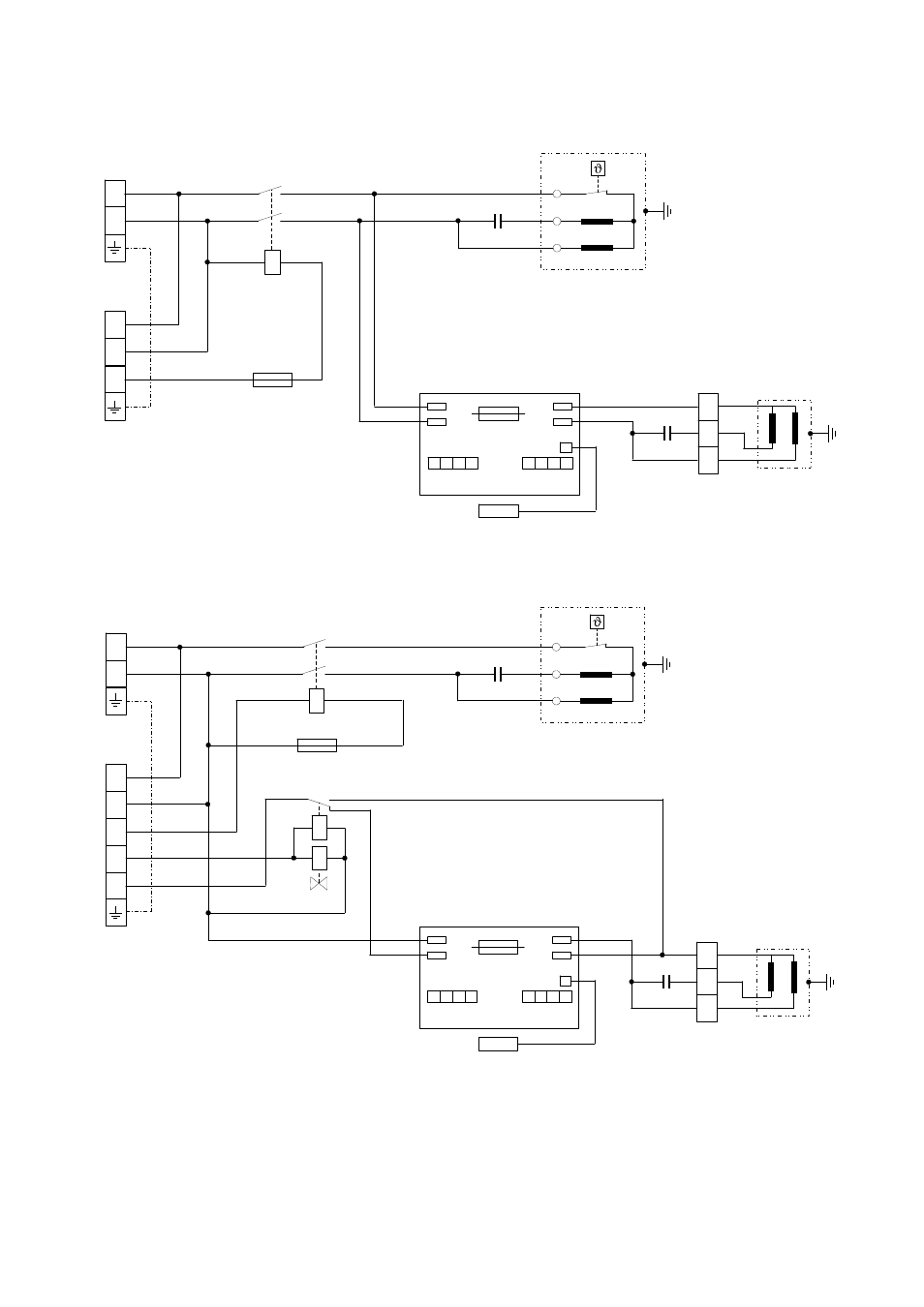
Legende:
TS1 = terminal strip
(
power supply)
TS2 = terminal strip (to indoor unit)
RV = reversal valve (only cooling / heating )
KCM1 = contactor
CM1 = motor (compressor)
VM = motor (ventilator)
C1 = capacitor
(compressor)
C3 = capacitor
(ventilator)
F1 = fuse (3 amp.)
Internal wiring diagram
Cooling / Heating units RKV 13 WH, RKV 24 WH
Internal wiring diagram
Cooling units RKV-K, RKV-W, RKV-T
We reserve the right to make changes to dimensions and design in the interest of technical progress.