Customer service and guarantee, Environment and recycling, Wiring diagram – REMKO RKS 510 User Manual
Page 13
13
The compressor starts a couple of minutes later
due to the delayed start of the outdoor part.
8. During the test run, check all regulating, control and
safety mechanisms to ensure that they are function-
ing and set properly.
9. Check the indoor unit’s control mechanism using
the functions described in the operating instructions.
Timer, temperature settings, fan mode and dehu-
midifying mode as well as all other mode settings
10. Measure overheating, outside, inside, outlet and
evaporation temperatures and enter these values in
the initial operation log.
11. Remove the manometer and reattach all parts that
were removed
Make sure that there are seals in the closing caps.
Operation/handling which does not comply with
these instructions is prohibited!
In cases of non-compliance, we assume no liability
and the guarantee becomes null and void.
Customer Service and
Guarantee
For the guarantee to be valid, the purchaser or his cus-
tomer must completely fill out the "guarantee certificate"
enclosed with all units and send it back to REMKO GmbH
& Co. KG
.
The units are repeatedly tested at the production site to
ensure that they are working properly. If a malfunction
occurs that cannot be eliminated by the operating per-
sonnel, please contact your dealer or contact person.
Proper use
The outdoor parts have been designed and fitted exclu-
sively for operation with REMKO indoor units belonging
to the RKV series.
The manufacturer assumes no liability for damage re-
sulting from non-compliance with manufacturer specifi-
cations and legal requirements, or if modifications are
made to the units.
Only authorised personnel may come into contact with
the cold cycle. This ensures that refrigerant does not es-
cape into the environment when the unit is being re-
paired.
Both the refrigerant and the system parts are subject to
special requirements for disposal.
Important information about recycling!
Environment and Recycling
The refrigerant in use is a safety refrigerant. This
means that, should damage occur, the quantities
released will not cause injury to the respiratory
systems of people and animals. Do not touch the
liquid refrigerant as it can freeze the skin!
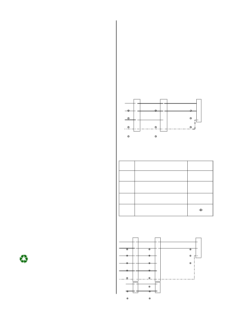
Wiring Diagram
Connections of the indoor unit RKV-K
The clamps of the indoor units can have different names
depending on the type of unit. The clamps of the RKV-K
unit have the following names:
RKV-K
Description
Outdoor part
R
Outer conductor
A
C
Neutral conductor
N
Y
Control conductor
compressor-contactor
2
PE
Protective conductor
Cooling units RKV-K, RKV-W, RKV-T
Red
White
Orange
Yellow /
green
Outdoor part
To the compressor
Protective conductor
Power supply
Indoor unit
A
N
2
L1
N
A
N
2
PE
PE
PE
Control
conductor
Neutral conductor
Outer conductor
230 V~,
50 Hz,
L1
N
PE
Cooling / Heating units RKV 13 WH, RKV 24 WH
L1
Red
White
Orange
Brown
Black
Yellow /
green
To the compressor
contactor
To the reverse valve
To the condenser
ventilator
Protective conductor
Indoor unit
Temperature
sensor
From
plug P6
A
N
4
2
3
PE
Power supply
N
PE
230 V~,
50 Hz,
L1
N
PE
Outdoor part
A
N
4
2
3
PE
Neutral conductor
Outer conductor