Electrical connection, Winter regulation – REMKO RKS 510 User Manual
Page 11
11
Prior to performing any work on the unit, it must be
unplugged from the power supply and secured
against being inadvertently switched on!
Connecting the outdoor part
Before proceeding with the connections, please read the
following instructions:
Electrical Connection
A power supply to the outdoor part must be installed as
well as a 4-wire control line for pure cooling operation
from the outdoor part to the indoor unit.
A 7-wire and a 2-wire control line is required between
the outdoor part and the indoor unit for cooling / heating
operation.
These electrical installations may only be performed by
authorised service personnel in accordance with the
relevant regulations.
Local guidelines for operation as well as the require-
ments established by local energy supply companies
must be observed for install and initial operation.
The connections of the outside part are located inside
the unit above the connection valves.
The power supply’s wire cross section is based on the
design specifications and the connection capacity of the
unit.
For the control circuit, we recommend using shielded
lines with a wire cross section of at least 1.5 mm².
◊
The connection box must be
installed close to the outdoor
part.
We recommend using a main
switch or a repair switch.
◊
Power for the indoor unit is
supplied via the connection line
from the outdoor part.
◊
Fuse protection for the system
occurs in accordance with the
technical data.
Proceed as follows to connect the line
1. Disassemble the unit cover by removing the fixing
screws.
2. Remove the side panel where the connection is lo-
cated.
3. Select the wire cross section of the connection line
based on the respective requirements.
4. Guide both lines through the rubber protective rings
of the fixed connection plate.
5. Clamp the lines as shown in the wiring diagram on
page 13.
6. Place the line securely in the strain relief and reas-
semble the unit.
Winter Regulation
To ensure that the system functions properly, the pres-
sure and temperature of the refrigerant must be kept
within the operating ranges in the indoor unit and out-
door part. The integrated winter regulation mechanism
makes it possible to keep operating ranges constant
even when outside temperatures go as low as –15 °C.
The winter regulation mechanism gradually adjusts the
condenser ventilator’s motor speed depending on the
operating pressure of the system and outside tempera-
ture. For this reason, the rotating motion of the ventilator
can be completely discontinued in winter.
The regulating mechanism consists of a regulating board
in a housing and a temperature sensor. The sensor rec-
ords the temperature of the air entering the condenser.
The regulating board regulates the starting voltage for
the ventilator depending on the regulating hysteresis set
by the two jumpers (JP).
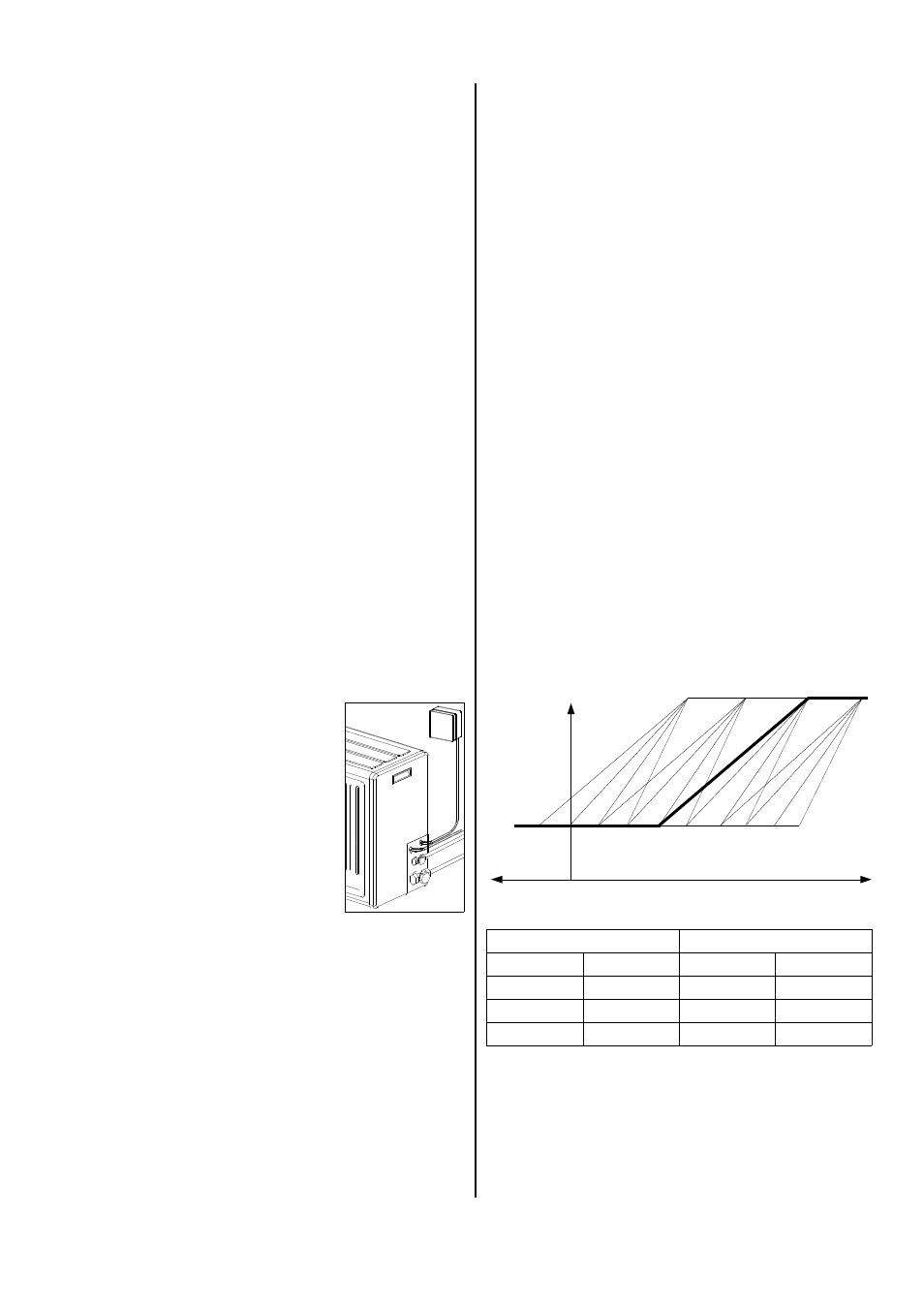
LVS
JP 1
10
JP 5
20
JP 2
15
JP 6
30
JP 3
20
JP 7
40
JP 4
25
JP 8
50
HVS
Adjusting the regulating hysteresis with the jumpers
HVS = Highest Ventilator Speed
HVS is the maximum ventilator speed for ventilation. It
is also called Effective Proportional Band (EPB).
LVS = Lowest Ventilator Speed
LVS is the design-specific, minimum ventilator speed
when the regulating board has a starting voltage of
35%. It is also called the Fixed Ventilator Voltage (FVV).
Starting voltage
35 %
(approx.80 V)
100 % (230 V)
5 10 15 20 25 30 35 40 45 50
0
-5
Temperature (°C)
HVS
20
HVS
30
HVS
40
HVS
50
LVS
10
LVS
15
LVS
25
LVS
25
Example:
Jumper JP 4 (LVS) and JP 7 (HVS) are plugged in.
◊
The maximum ventilator speed is reached at a tem-
perature of 40 °C.
◊
The minimum ventilator speed is set at a tempera-
ture of 15 °C.