V. installation – Posiflex TM-6100 User Manual
Page 4
4
V.
INSTALLATION
A. For TM6112
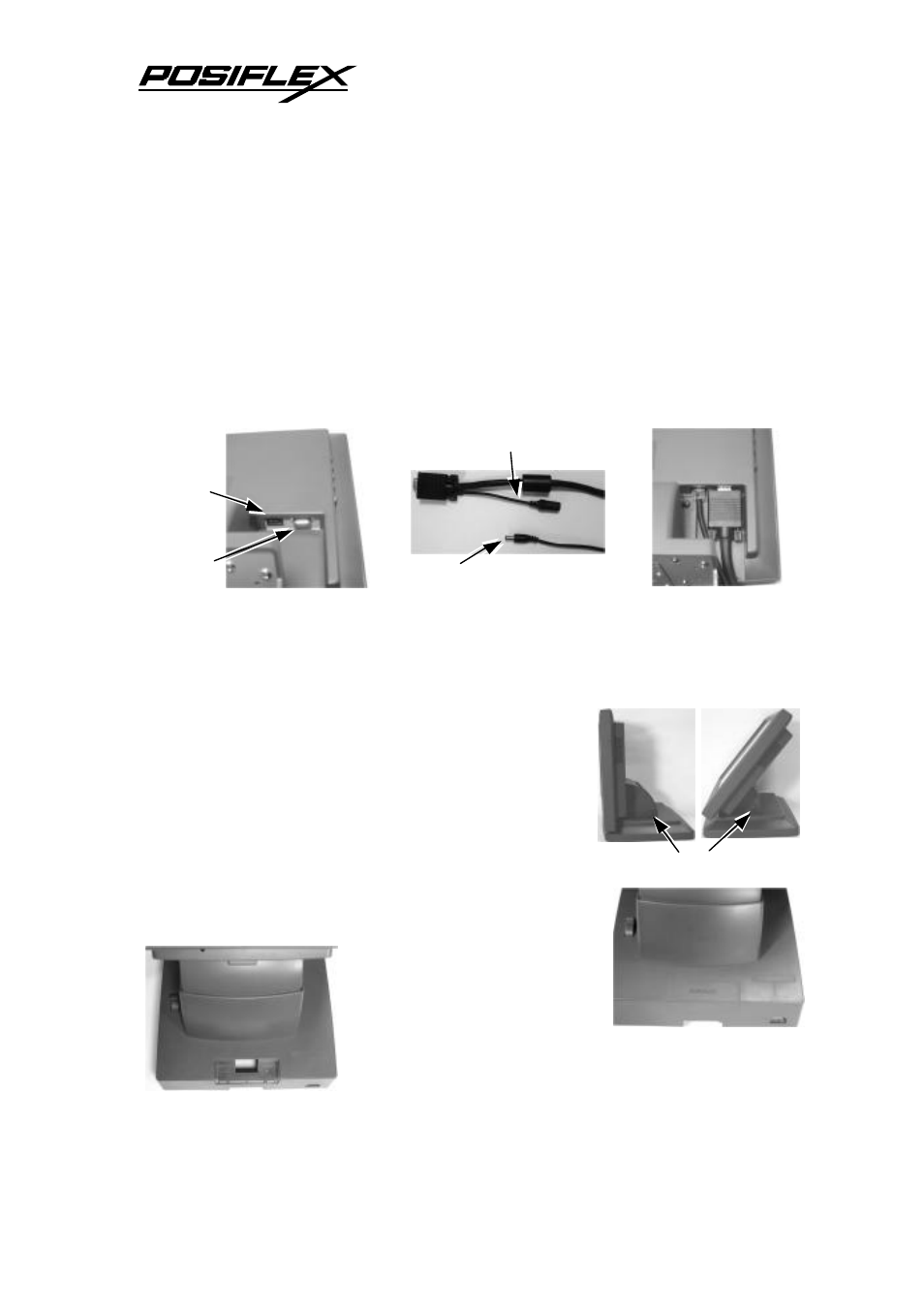
1. Find in the rear of the panel a 10 pin RJ-45 jack for touch controller
connection and a VGA connector.
2. Connect the 10 pin RJ45 plug end of the touch control cable to the jack till it
clicks. Connect and screw fix the end with power connector of VGA cable as
in the picture.
3. Connect and screw fix the other end of touch control cable to an appropriate
COM port and the VGA cable to VGA port of the host system.
4. Check the specification of the power adaptor against the power socket then
insert the power adaptor into the power socket.
Connect the output plug from the power adaptor to
the connector in VGA cable
5. Press in the adjust button when turning the LCD
panel for best viewing effect in application.
B. For TM6101
1. First remove the rear connect cover from the
TP7000 series base stand. Please refer to TP7000
User’s Manual and hold
your thumb gently on the
outer surface of the rear
connect cover while
having your middle finger
inside the stand assembly through the cable
exit to pull the plastic hook plate of the rear
Adjust Button
Touch
Control
VGA
Plug from Adaptor
Power Connector
Back of TM6112
One end of VGA cable
Cables connected
Rear side of TP7000 base
Rear connect cover removed