Installation, Continued – Desa CGMFP User Manual
Page 11
www.desatech.com
119315-01A
11
iNsTallaTioN
Continued
Actual Framing
Height
3
3
/
4
"
1
/
4
"
Front Width 19
3
/
4
"
1
1
/
"
Depth
8
/
8
"
8
/
8
"
Bottom
0"
0"
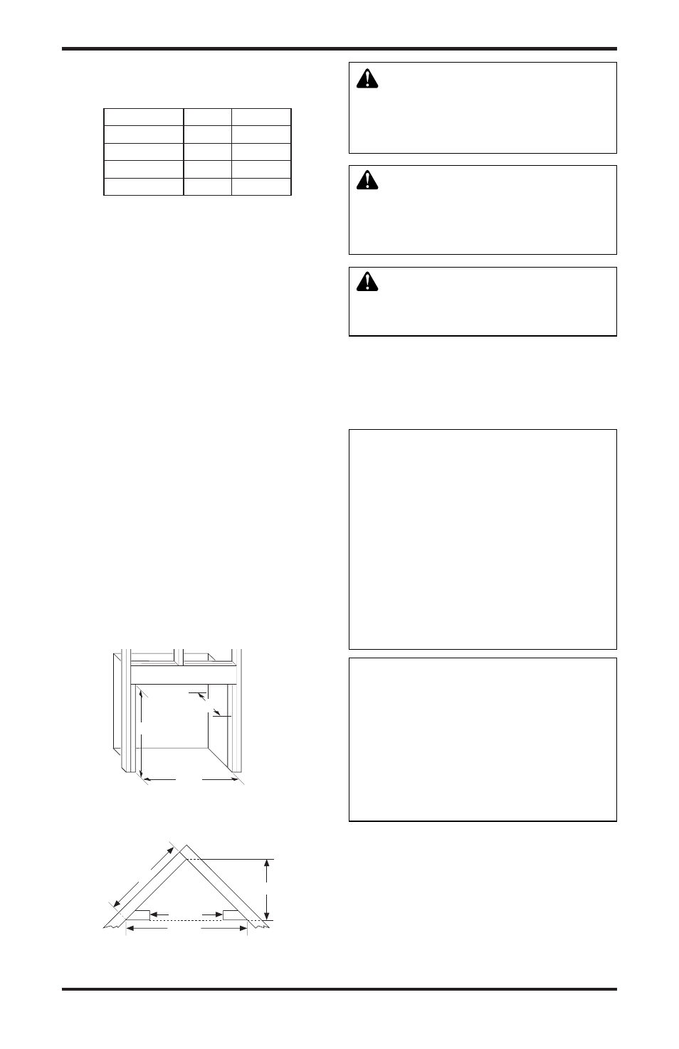
1. Frame in rough opening. Use dimensions shown
in Figure 7 for the rough opening. If installing in
a corner, use dimensions shown in Figure 8 for
the rough opening. The height is 22
1
/
4
" which
is the same as the wall opening above.
2. Install gas piping to fireplace location. This
installation includes an approved flexible gas
line (if allowed by local codes) after the equip-
ment shutoff valve. The flexible gas line must
be the last item installed on the gas piping.
3. If you have not assembled firebox, follow
instructions on page 6.
4. Carefully set fireplace in front of rough opening
with back of fireplace inside wall opening.
5. Attach flexible gas line to fireplace gas regula-
tor. See Connecting Fireplace to Gas Supply,
page 14.
6. Check all gas connections for leaks. See
Checking Gas Connections, page 15.
IMPORTANT:
When finishing your firebox,
combustible materials such as wall board, gypsum
board, sheet rock, drywall, plywood, etc. may be
butted up next to the sides and top edge of the fire-
box. Combustible materials should never overlap
the firebox front facing.
17
1
/
2
"
22
1
/
4
"
8
7
/
8
"
Figure 8 - Rough Opening for Installing
in Corner
Figure 7 - Rough Opening for Installing
in Wall
29
7
/
8
"
21
1
/
8
"
42
1
/
4
"
17
1
/
2
"
WARNING: Do not allow any
combustible or noncombustible
materials to overlap the firebox
front facing.
WARNING: Do not allow
noncombustible materials to
cover any necessary openings
like louvered slots.
WARNING: Never modify or
cover the louvered slots on the
front of the firebox.
Mantel Clearances for Built-In
Installation
If placing mantel above built-in fireplace, you must
meet minimum clearance between mantel shelf and
top of fireplace opening.
NOTICE: Surface temperatures
of adjacent walls and mantels
become hot during operation.
Walls and mantels above the
firebox may become hot to
the touch. If installed properly,
these temperatures meet the
requirement of the national
product standard. Follow all
minimum clearances shown in
this manual.
NOTICE: If your installation
does not meet the minimum
clearances shown in Figure 9,
page 12, you must do one of the
following:
• raise the mantel to an accept-
able height
• remove the mantel