ONICON F-5200 Insertion User Manual
Page 11
11451 Belcher Road South, Largo, FL 33773 • USA • Tel +1 (727) 447-6140 • Fax (727) 442-5699 • [email protected]
F-5200 Insertion Thermal Mass Flow Meter Manual 05/14 - 0756-8 / 19475
Page 11
3.1 INSTALLATION SITE SELECTION
Install the flow meter where it will be accessible for personnel to perform necessary periodic
maintenance. The clearance required for installation is typically 30-36” from the pipe wall
to the nearest obstruction above the valve assembly. This clearance dimension will increase
with larger diameter pipes. Refer to Section 1.6 WORKING ENVIRONMENT for additional
considerations.
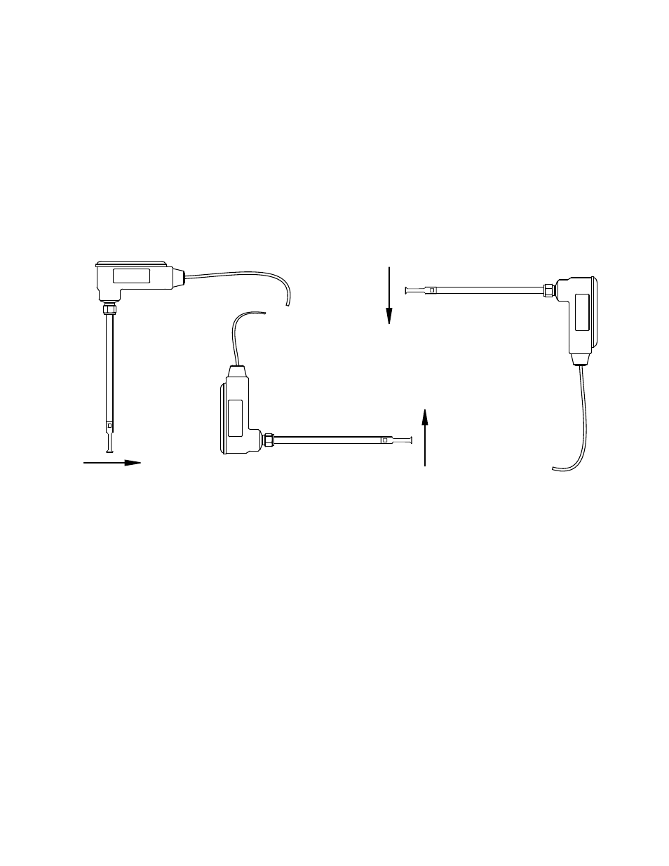
ONICON insertion style flow meters must also be correctly oriented in the pipe with respect
to the direction of flow.
The drawings above illustrate the relationship between flow direction and the orientation of the
meter when installed in the pipe. Contact ONICON for assistance if this relationship does not
allow for proper installation.
GENERAL PRACTICES:
1.
For best results, install the flow meter in a straight run of pipe, free of bends, tees,
valves, transitions and obstructions.
2.
Straight run requirements vary based on the nature of the upstream obstruction.
See the table on page 12 for guidelines in determining upstream straight run
requirements. Depending upon specific location details, more or less straight run
may be required to produce a satisfactory flow profile.
3.
If there is insufficient straight run, allow 80% of the run upstream and 20% of
the run downstream. If the total length of straight run is less than 75% of the
recommended distance, performance may seriously degrade, and consideration
should be given to installing a flow conditioner.
Flow Direction
Flow Direction
Flow Direction
The drawings above illustrate the relationship between
flow direction and display orientation for standard meters.
ONICON
ONICON
ONICON