Olson Technology CAN User Manual
Page 5
025-000570 Rev. X7
www.olsontech.com
5
TRANSMITTER DESCRIPTION
The Advanced L-Band Transmitter carries 10MHz to 4,000MHz RF signals over single-mode
optical fiber. Model OLAT includes an adjustable 25dB digital gain control. Laser power op-
tions include +4dBm/2.5mW (DFB, CWDM), +5dBm/3mW (DFB) or +10dBm/10mW (DFB,
DWDM). The transmitter offers two LNB powering options. The LNB may be powered
through a standard “F” connector with a power supply or power inserter or via the
OTAPS-4000 power supply through a 9-pin DIN connector. The OTAPS-4000 has selector
switches allowing each transmitter to have its LNB voltage set at +13V or +17V and also to
turn a per-channel 22kHz tone on or off. The LNB Current is limited to about 0.5 Amps. Any
attempt to draw more than 0.5 Amps will cause the LNB voltage to be pulsed at a 0.1% duty
cycle until the current drops below 0.5 Amps. Built-in test points, LED indicators and alarms
allow the transmitter to be easily set up and maintained.
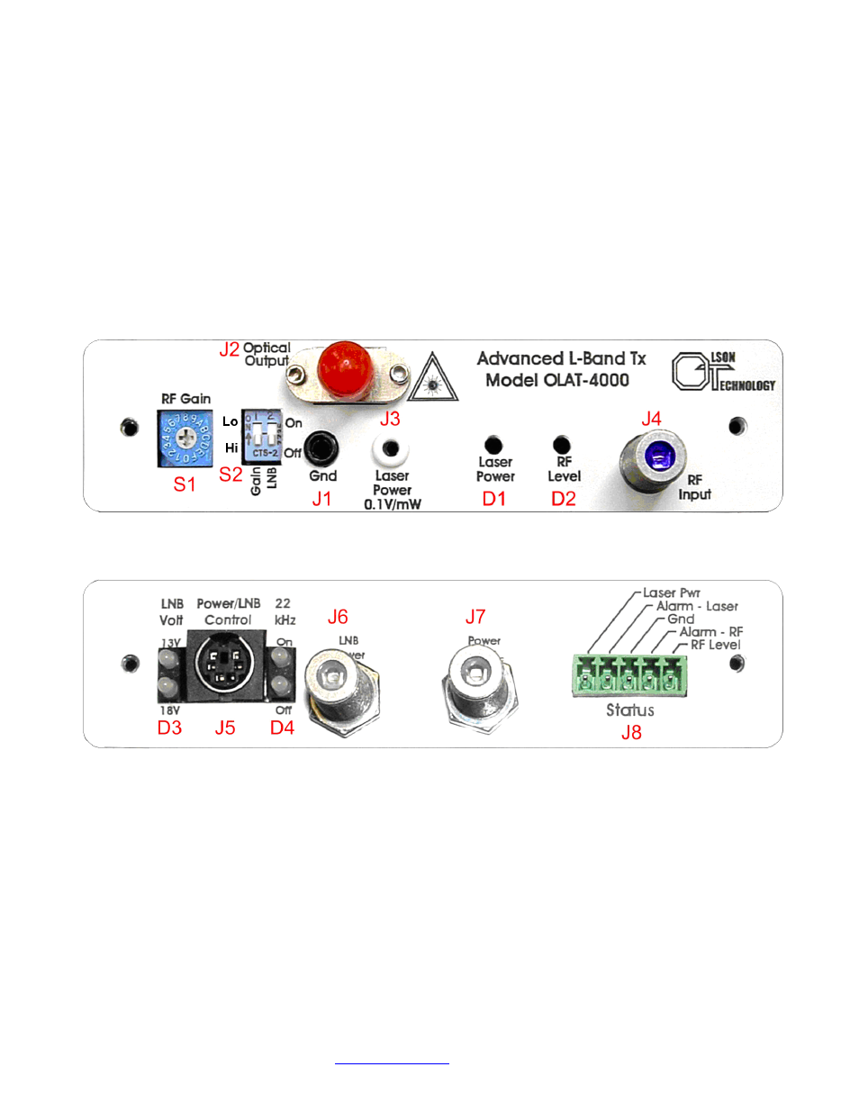
Figure 1 - Front & Rear View of Transmitter
TRANSMITTER CONTROLS OVERVIEW
On the front of the transmitter, the user can change the gain of the transmitter over a 25dB
range using S1 & S2. Higher gain allows the transmitter to be used with lower level RF sig-
nals and vice versa. S1 is a 16-position, hexadecimal, rotary switch. The “0” setting is mini-
mum gain and the “F” setting is the maximum gain. Each position is equal to a 1dB gain
change. So the gain of the “F” setting compared to the gain of the “0” setting will be 15dB
higher. The left switch of S2 is a high/low gain setting. When it is in the “Lo” position, the in-
cremental gain is 0dB. When it is “Hi” position, the gain increases by 10dB. To set the trans-
mitter for minimum gain, set S1 to “0” and the left switch of S2 up. To set the transmitter for