6 squelch vox circuitry and jumper settings, 1 cover removal, 2 squelch disable logic polarity jumpers – Northern Airborne Technology CC250 User Manual
Page 16
CC450-0V2 Communications Controller
Installation and Operation Manual
2.6
Squelch VOX Circuitry and Jumper Settings
CAUTION:
The Squelch VOX circuitry adjustments are only accessible by removing the top
cover of the unit. As this unit contains electrostatic discharge sensitive
components, this should only be undertaken by a certified technician at a static
protected workstation.
2.6.1
Cover Removal
Refer to Exploded View CC450\904-1 for enclosure removal.
a) Remove the four jackposts from the back of the unit using a 3/16" driver or socket.
b) Remove the two Phillips countersunk screws from each side of the unit.
c) Carefully slide the cover back (to clear the connectors) and upwards. It may be difficult to grip the
cover and gentle prying from behind the front plate may be required.
2.6.2
Squelch Disable Logic Polarity Jumpers
These jumpers determine if the Squelch Disable line will be active low (grounded = on) or active high
(voltage = on) logic polarity. Normally this jumper is set to the active low position for all transceivers. The
only exception is the Wulfsberg FF40 series transceivers, which use the active high position.
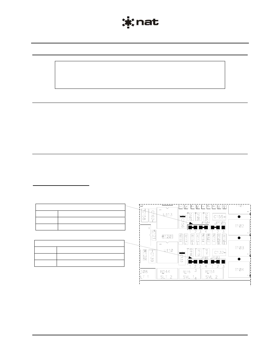
2.6.2.1
Main Board
The diagram below shows the applicable section of the main board.
Jumper JP102 (RT1)
Position Squelch Disable Logic Polarity
1-2, 3-4 Active Low (Normal Position)
1-3, 2-4 Active High
Jumper JP104 (RT2)
Position Squelch Disable Logic Polarity
1-2, 3-4 Active Low (Normal Position)
1-3, 2-4 Active High
Page 2-6
Issue 1
Section 2 Rev: 1.00
ENG-FORM: 805-0114.DOT
CONFIDENTIAL AND PROPRIETARY TO NORTHERN AIRBORNE TECHNOLOGY LTD.