5 mechanical mounting, 5 adjustments and connections, 1 squelch logic threshold adjustments – Northern Airborne Technology CC250 User Manual
Page 14
CC450-0V2 Communications Controller
Installation and Operation Manual
2.4.5
Mechanical Mounting
The CC450-0V2 requires a standard Dzus rail assembly with an opening width of 5.0” and a front
clearance width of 5.75”. The height requirement is 0.75”. Be sure that adequate clearance is allowed for
the cable connections at the rear of the unit.
Note:
Ensure that proper mechanical support is provided under the chassis. Due to the shallow profile of
the unit, the Dzus fasteners should not be relied upon for complete mechanical support. NAT Ltd
recommends that it should be mounted above another unit, such as a control head, to provide
better mechanical support.
2.5
Adjustments and Connections
CAUTION
Incorrect setting of these adjustments may cause improper operation of
the CC450-0V2 during relay operations.
These adjustments have been factory set to operate correctly with NAT NT-Series, NTX-Series, NPX-
Series and NCT-Series, Wulfsberg Flexcomm, and Wulfsberg RT9600/7200 transceivers. For any
other manufacturer's radios, consult NAT Ltd.
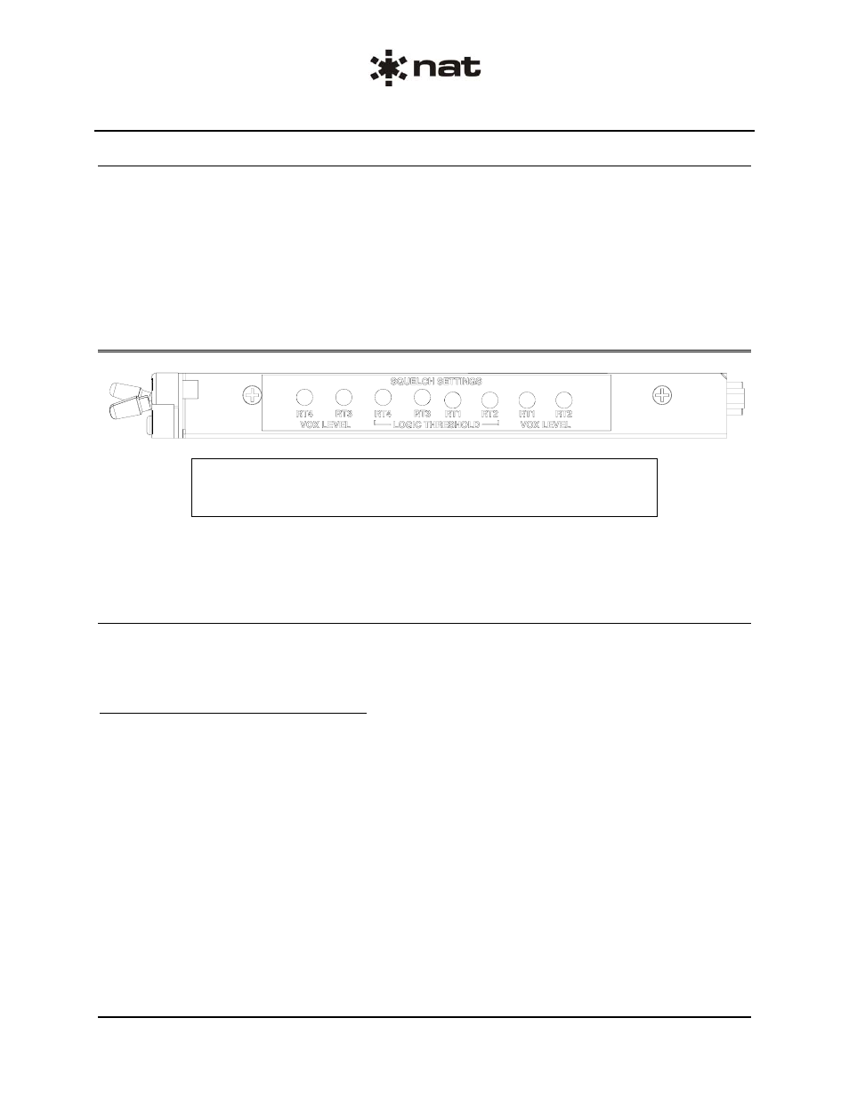
2.5.1
Squelch Logic Threshold Adjustments
The Squelch Logic Threshold settings control the voltage at which the CC450-0V2 recognizes that the
Squelch Disable line has gone active (the transceiver is receiving). It is normally set to 1.0 Vdc Active Lo
or grounded signal.
2.5.1.1
'Active Lo' Squelch Disable
a) Put all the CC450-0V2 Transceiver Select switches in the down (inactive) position.
b) Power up the CC450-0V2 by putting the Power switch in the up (ON) position
c) Turn the Squelch Logic Threshold Adjustment fully counterclockwise (ccw).
d) Slowly turn the adjustment clockwise (cw) until the stops are reached or the RX/TX annunciator on
the CC450-0V2 lights ORANGE.
e) Take note of the adjustment position
f) While depressing the Squelch Test button for the respective transceiver, rotate the adjustment ccw until
the stops are reached or the RX/TX annunciator goes out.
g) Take note of the adjustment position
h) Release the Squelch Test button.
i) Position the adjustment half way between the positions reached in steps e) and g).
Page 2-4
Issue 1
Section 2 Rev: 1.00
ENG-FORM: 805-0114.DOT
CONFIDENTIAL AND PROPRIETARY TO NORTHERN AIRBORNE TECHNOLOGY LTD.