Step 2 – wiring the nortec links 2 module – Nortec LINKS 2 SETC B+ User Manual
Page 9
5 | Links 2 Retrofit for GSTC / SETC B+, NHTC, NHRS
Step 2 – Wiring the Nortec Links 2 Module
1 Most of the wiring connections for the new Nortec LINKS 2 module will have already been
finished at the factory; however, there are a few connections that will need to be made to
connect the unit the GS/SE series humidifier. Refer the LINKs 2 wiring diagram included in
the package for details.
2 Module Power Connections: There will be a wire harness provided that will consist of a red
and blue wire. Both red and blue wires are terminated with a ring terminal.
a The ring terminal of the red wire is to be connected to the power terminal on the 24V
side of the transformer located at the bottom, left of the electrical compartment.
b The ring terminal of the blue wire is to be connected to the ground terminal on the 24V
side of the transformer.
3 Humidifier Communication Connection: On the Nortec LINKS 2 assembly there will be a
CAT5 cable with RJ45 connector.
a This connector is to be plugged into the jack on the bottom right side of the humidifier
main PCB board.
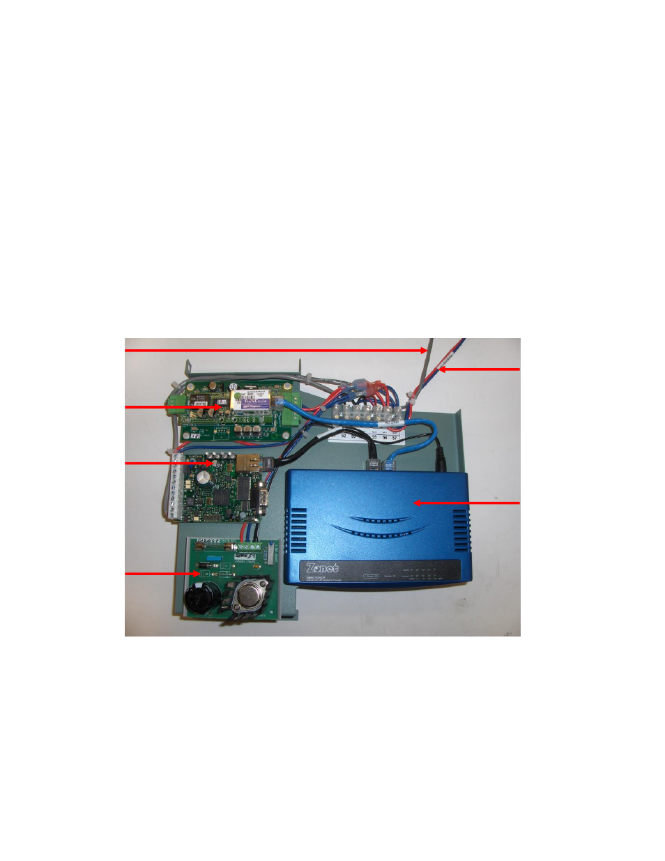
Figure 6: Component Identification
LAN Router or
Switch
(BACnet/IP)
OnLine
Module
LINKS 2
Module
Router
Power
Supply
CAT5
cable
Red and blue
wires