Nevion SPG-AVA-DMUX User Manual
Page 16
SPG-AVA-DMUX
Rev. C
nevion.com | 16
switch to the next priority and look for a signal there, and so on. If
the user doesn’t want to
use all three priority levels, the unused ones can
be set to ‘–‘. Should the user specify a list
of priorities where it is actually impossible to reach one or both of the backup levels (because
the main input is selected to be an internal generator, and therefore always present), the card
will also display the unreachable levels as
‘–‘. The most typical setups will be as follows:
Electrical
→ Video gen. → ‘–‘
(Internal generator as fallback for the Electrical input)
Optical
→ Video gen. → ‘–‘
(Internal generator as fallback for the Optical input)
Electrical
→ Optical → Video gen. (Optical as fallback for the Electrical input, and internal
generator as final fallback)
Optical
→ Electrical → Video gen. (Electrical as fallback for the Optical input, and internal
generator as final fallback)
The generated video will be black. The internal video generator in the setups above can be
replaced with Mute, which will turn the output drivers off when the input diappear. If internal
video generator above is replaced with
‘–‘, no special action will be taken when the inputs(s)
disappear, the output will just frame-freeze forever/until a valid input is again detected.
The switching is always latching. This means that when both physical inputs are missing,
then the module will look for a valid input in the background. But if there is a signal on the
physical input selected as first fallback, then the module will not go back to the input selected
as main unless the fallback disappears. The user can however force the module back to main
by pressing the latch Reset button.
Hold time and lock time can also be adjusted. These specify how long a signal can be missing
before the next input in the prioritized list is attempted, and how long a lost signal has to be
present before it is considered OK again, respectively.
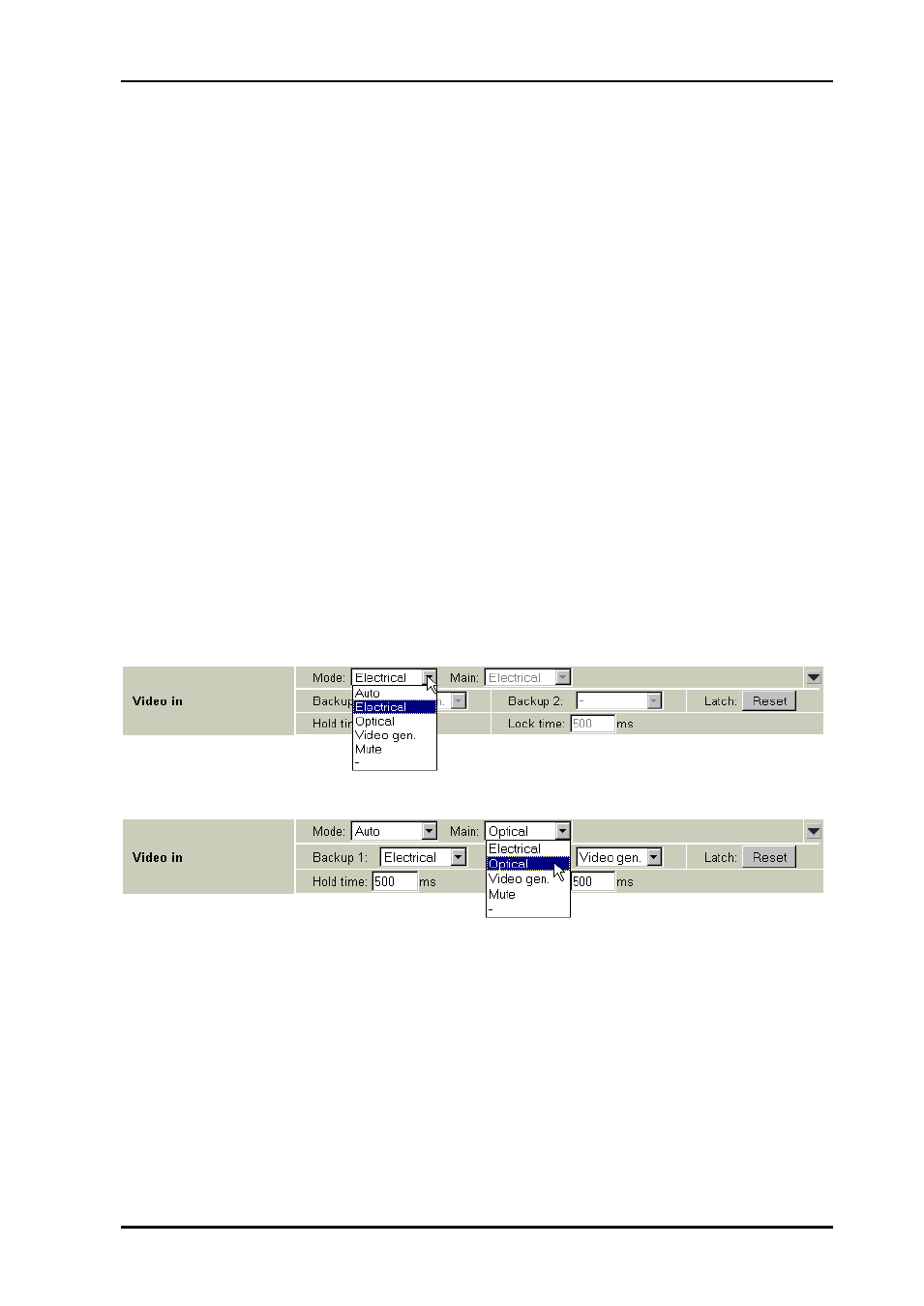
Figure 9: Multicon GYDA view of electrical input selected manually
Figure 10: Multicon GYDA view of the auto mode input selection