Reference: installing linear scales, Installation of linear scales, Positioning the scale – MicroE 1500V Mercury User Manual
Page 14: Mounting the scale
Reference Section
Installation of Linear Scales
Page
12
MicroE Systems
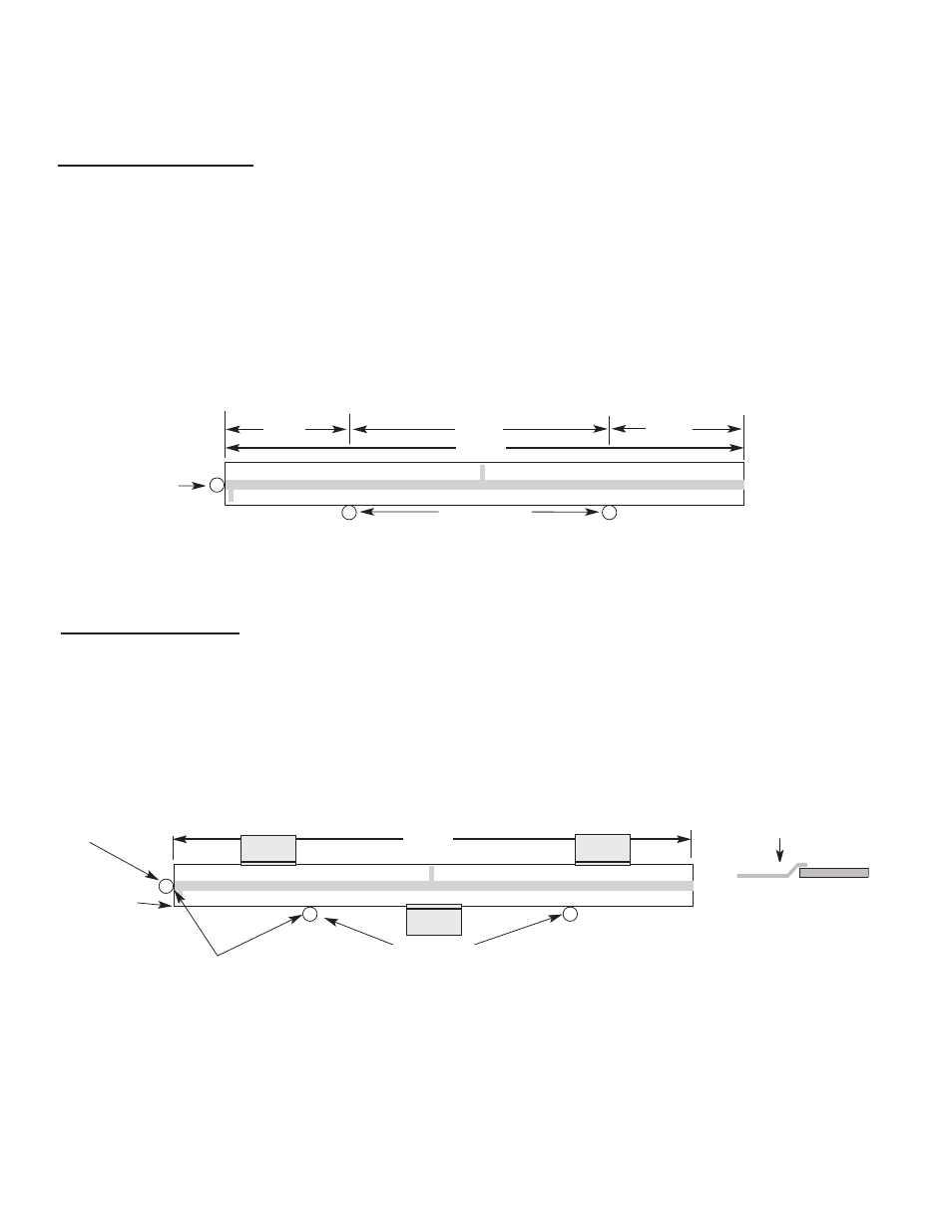
L
0.2L
0.6L
0.2L
Benching pins
Positioning the Scale
Note: Before beginning mounting procedure, use talc-free gloves or finger cots to handle the scales. Also use vacuum compatible handling procedures and materials .
"Benching" the scale to the system means aligning the scale by means of benching pins. Pin locations are described on the appropriate interface drawing.
Two benching pins are recommended on the long side of the scale and one at the end as shown . This is marked datum A on the interface drawing.
Position the benching pins in from either end. 20% of the overall
scale length is the recommended location from the edge.
Be sure the benching pins do not extend too high in the Z direction to
prevent mechanical interference with the sensor or sensor mount.
2
1
End
Benching
Pin
Mounting the Scale
End Benching
Pin
Hard epoxy
at one corner,
this end only.
Suggested Epoxy and Clamp Mounting
1
Make sure the mounting surface is
clean and dry.
Scale clamps (customer supplied) may be used to mechanically secure the
scale. The clamps should allow for thermal expansion of the scale and
mounting surface. Make sure that the clamps do not interfere with the sensor
or sensor mount. Note: adhesive used on clamps supplied by MicroE is not
vacuum rated.
Side view showing
suggested scale
clamps and scale.
Space clamps every
75mm on scales over
150 mm in length.
4
Apply a hard, vacuum compatible epoxy to the
end of the scale at the end benching pin.
3
MicroE Systems
L
2
Align the scale by placing the edges
against the benching pins.
Benching pins
Scale clamp
Mounting clamp
Mounting clamp
Mounting clamp