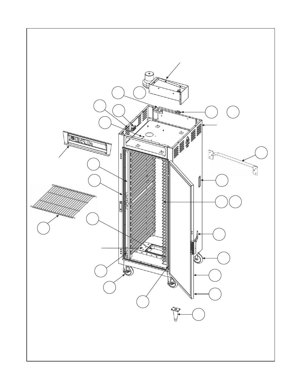
Service and replacement parts, Continued) – Metro С5 8 Series Controlled Temperature Heated Holding Cabinets User Manual
Page 15
This manual is related to the following products:
See also other documents in the category Metro Furniture:
- Mobile Garment Rack (4 pages)
- Mobile Garment Rack (4 pages)
- Mobile Garment Rack (2 pages)
- Mobile Garment Rack (4 pages)
- Mobile Garment Rack (5 pages)
- MetroMax iQ Universal Divider (2 pages)
- MetroMax iQ Universal Divider (2 pages)
- Starsys Overbridge (6 pages)
- 4 Series Insulation Armour Plus Hot food Holding Cabinets (16 pages)
- Casters, Rigid (8 pages)
- MetroMax iQ Accessories Wire Basket and Divider (1 page)
- Power Strip / Cord Wrap Mounted on Overbridge (2 pages)
- medDISPENSE (9 pages)
- T-Series Hot Food Holding Cabinets (24 pages)
- BACKBOARD (LEC308/309) (1 page)
- Case Cart Static Dissipative Cable (2 pages)
- 3-Sided Snake Frame (6 pages)
- 3-Sided Snake Frame (15 pages)
- MetroMount Large CPU Cradle (1 page)
- MetroMount Slimline (WMF-SL02) (2 pages)
- Passive Lock System Seals PSLK (1 page)
- Pizza Prep Station (1 page)
- C5 1 Series Heated Cabinets (32 pages)
- Metropolitan Home Shelving (2 pages)
- Stem Caster Shimmey Damper (1 page)
- 1800 Series Mobile Workstation (40 pages)
- Dorm Space Saver (1 page)
- Food Prep Station (1 page)
- Lifeline Emergency Cart (2 pages)
- 3-Sided Snake Frame (1 page)
- 3-Sided Snake Frame (4 pages)
- 3-Sided Snake Frame (6 pages)
- 3-Sided Snake Frame (4 pages)
- Polymer Caster (1 page)
- Order Prep/Pick Station (1 page)
- Professional's Choice Wall Mounted Shelves (4 pages)
- MetroMax i Intermediate S-Hook Kit (1 page)
- Casters, Rigid (4 pages)
- Casters, Rigid (3 pages)
- Carts, High Profile Utility, Polymer (2 pages)
- Drive Through/Drink Dispensing Station (1 page)
- Deep Ledge Utility Cart (4 pages)
- Mounting Post to Dolly - “B” PLATE CASTER (2 pages)
- MetroMax iQ Universal Divider (1 page)
- Carry-Out Worktable (Pass Through) (1 page)