Specifications, Digital input/output, Counter – Measurement Computing PC-CARD-D24/CTR3 User Manual
Page 16: Chapter 4
Chapter 4
Specifications
Typical for 25 °C unless otherwise specified.
Specifications in italic text are guaranteed by design.
Digital input/output
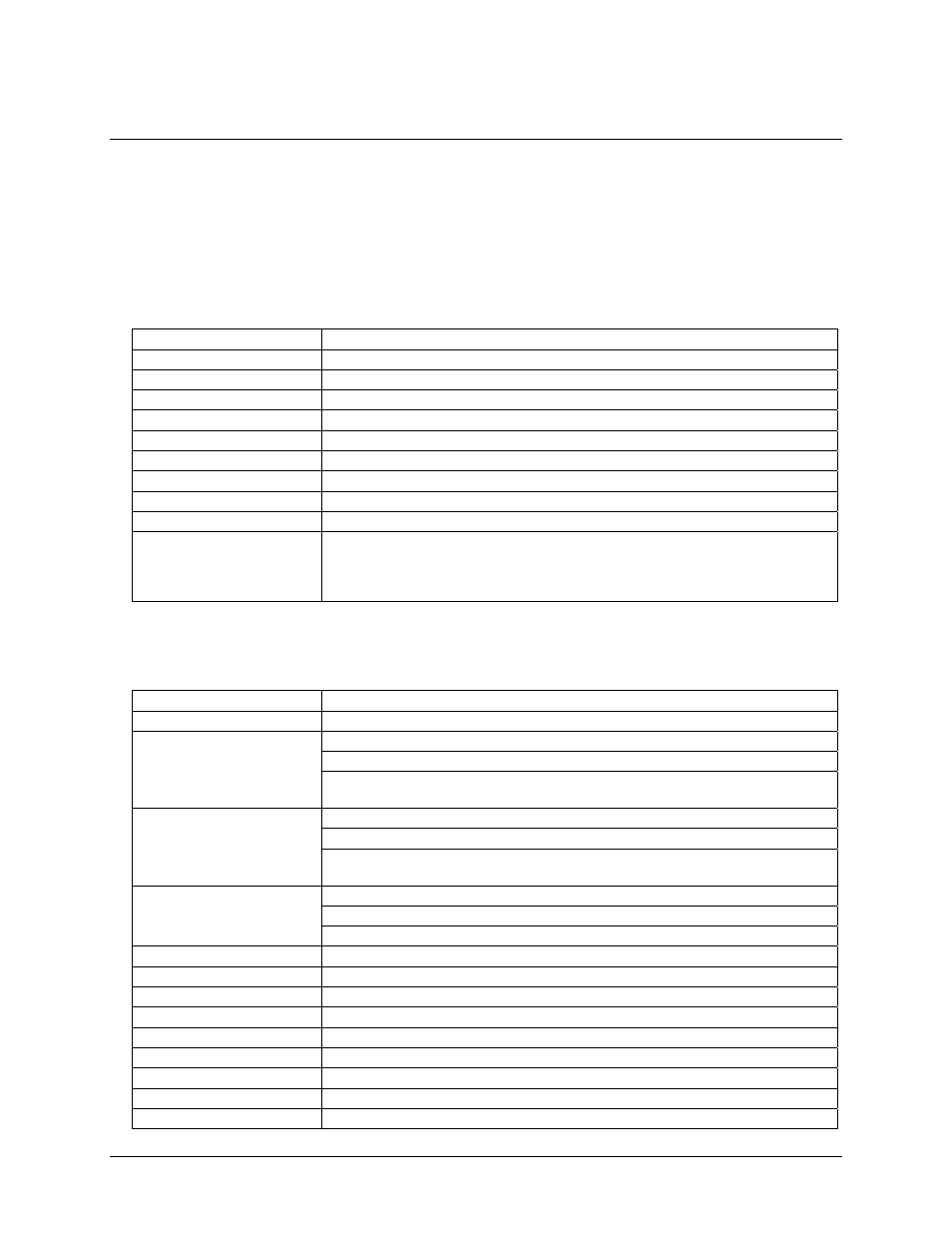
Table 1. Digital I/O specifications
Digital type
82C55
Configuration
2 banks of 8, 2 banks of 4, programmable by bank as input or output
Number of channels
24 I/O
Output high
3.0 volts min @ -2.5 mA
Output low
0.4 volts max @ 2.5 mA
Input high
2.0 volts min, 5.5 volts absolute max
Input low
0.8 volts max, -0.5 volts absolute min
Power-up / reset state
Input mode (high impedance)
Interrupts
Programmable levels 2-15
Interrupt enable
Programmable
Interrupt sources
Programmable:
External (Ext Int)
Internal (counter 1 output, counter 2 output, counter 3 output, 82C55 port C bit C0 or
bit C3)
Counter
Table 2. Counter specifications
Counter type
82C54
Configuration
3 down counters per 82C54, 16 bits each
Source:
Programmable internal 10 MHz or external (CTR1 CLK)
Gate:
External (CTR1 Gate), pulled high (enabled) by 10 k resistor
Counter 1 - Independent user
counter
Output:
Available at user connector (CTR1 Out), may also be programmed to
connect to counter 2 clock.
Source:
Programmable internal 10 MHz , external (CTR2 CLK) or CTR1 Out
Gate:
External (CTR2 Gate), pulled high (enabled) by 10 k resistor
Counter 2 - Independent user
counter
Output:
Available at user connector (CTR2 Out), may be programmed to
connect to counter 3 clock
Source:
Programmable internal 1 MHz , external (CTR3 CLK) or CTR2 Out
Gate:
External (CTR3 Gate), pulled high (enabled) by 10k resistor
Counter 3 - Independent user
counter
Output:
Available at user connector (CTR3 Out)
Clock input frequency
10 MHz max
High pulse width (clock input)
30 ns min
Low pulse width (clock input)
50 ns min
Gate width high
50 ns min
Gate width low
50 ns min
Input low voltage
0.8 V max
Input high voltage
2.0 V min
Output low voltage
0.4 V max
Output high voltage
3.0 V min
16