Measurement Computing PC-CARD-D24/CTR3 User Manual
Page 12
PC-CARD-D24/CTR3 User's Guide
Installing the PC-CARD-D24/CTR3
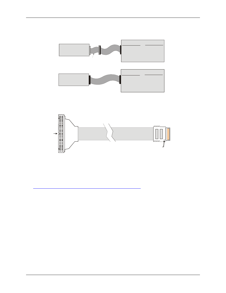
Figure 6. Connecting to screw terminal or relay boards
shows a map of the two methods of cabling the PC-CARD-D24/CTR3 to various screw terminal or
signal conditioning boards.
C50FF-#
TERMINALS
CIO-MINI50
CIO-SPADE 50
CIO-TERM100
SCB-50
RELAYS
SSR-RACK24
CIO-ERB24
CIO-SERB24
PC-CARD-D24/CTR3
CPCC-50M-4
TERMINALS
CIO-MINI50
CIO-SPADE 50
CIO-TERM100
SCB-50
RELAYS
SSR-RACK24
CIO-ERB24
CIO-SERB24
PC-CARD-D24/CTR3
CPCC-50F-39
OR
CPCC-50F-39
50-pin female IDC connector.
50
49
2
1
Dot
50-pin micro connector.
Connect to the I/O connector
on the PC-CARD
with the dot facing UP.
Key
50
1
Figure 7. CPCC-50F-39 cable connections
Details on the CPCC-50F-39 cable are available on our web site at
12
See also other documents in the category Measurement Computing Hardware:
- ACC-300 (7 pages)
- AI-EXP32 (20 pages)
- AI-EXP48 (19 pages)
- BTH-1208LS (30 pages)
- 6K-ERB08 (32 pages)
- BTH-1208LS Quick Start (4 pages)
- 6K-SSR-RACK08 (33 pages)
- BTH-1208LS-OEM (27 pages)
- CB-COM-Digital (68 pages)
- CB-7018 (68 pages)
- CB-7000 Utilities (44 pages)
- CB-7080D (74 pages)
- CB-COM-7033 (44 pages)
- CB-COM-7017 (72 pages)
- CB-COM-7024 (76 pages)
- CB-NAP-7000P (36 pages)
- CIO-DAC02/16 (16 pages)
- CIO-DAC02 (18 pages)
- CB-NAP-7000D (56 pages)
- CIO-DAC16-I (16 pages)
- CIO-DAC16/16 (20 pages)
- CIO-DAS08 (21 pages)
- CIO-DAC16 (20 pages)
- CIO-DAS08/JR (16 pages)
- CIO-DAS08/JR/16 (14 pages)
- CIO-DAS08/JR-AO (16 pages)
- CIO-DAS08-AOM (32 pages)
- CIO-DAS08-PGM (28 pages)
- CIO-DAS16/330 (34 pages)
- CIO-DAS48-I (17 pages)
- CIO-DAS16/M1 (38 pages)
- CIO-DAS48-PGA (18 pages)
- CIO-DAS800 (20 pages)
- CIO-DAS802/16 (22 pages)
- CIO-DAS6402/16 (40 pages)
- CIO-DAS-TEMP (20 pages)
- CIO-DDA06/16 (18 pages)
- CIO-DDA06/JR (17 pages)
- CIO-DIO24H (20 pages)
- CIO-DIO24/CTR3 (21 pages)
- CIO-DI192 (24 pages)
- CIO-DDA06 (21 pages)
- CIO-DIO48 (19 pages)
- CIO-DO192H (16 pages)
- CIO-DIO192 (20 pages)