Interrupt level select jumper, Wait state jumper – Measurement Computing CIO-CTR05 User Manual
Page 11
CIO-CTR05 User's Guide
Installing the CIO-CTR05
11
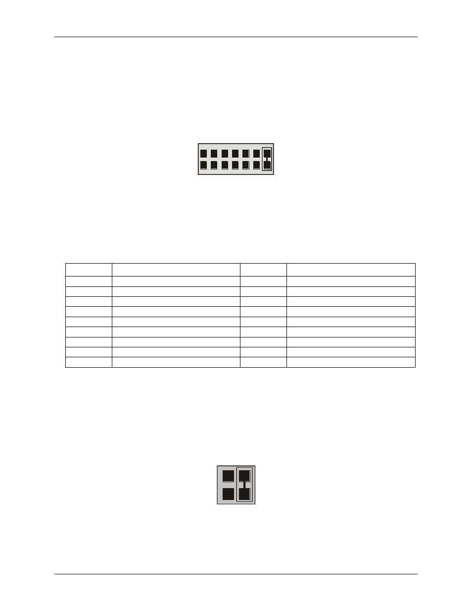
Interrupt level select jumper
Use the Interrupt Level Select jumper located above the PC bus interface (gold pins) to set the IRQ number you
want the interrupt pulse on.
This jumper is set by default with no interrupt level set ("X" position). Interrupts are hardware initiated
software routines and are described in the section on programming.
2 3 4 5 6 7 X
IR1
Figure 2. Interrupt Level Select jumper
Pin 1 (IR INPUT) of the 37-pin connector is an input jumper which maps the interrupt directly onto the PC bus.
The signal to the bus is buffered. The buffer is enabled by a TTL low level on Pin 2 (IR ENABLE).
Hardware interrupts assigned by the PC may be available; refer to the following table. Note that IRQ8 to IRQ15
are AT only.
Name
Description
Name
Description
NMI
Parity
IRQ8
Real Time Clock (AT)
IRQ0 (AT)
Timer
IRQ9
Re-Directed To IRQ2
IRQ1
Keyboard
IRQ10
Unassigned
IRQ2
RESERVED (XT) INT 8-15 (AT)
IRQ11
Unassigned
IRQ3
COM OR SDLC
IRQ12
Unassigned
IRQ4
COM OR SDLC
IRQ13
80287 Numeric CO-P
IRQ5
Hard Disk (AT) LPT (AT)
IRQ14
Hard Disk
IRQ6
Floppy Disk
IRQ15
Unassigned
IRQ7
LPT
Wait state jumper
The CIO-CTR05 board has a wait state jumper which you can set to enable an on-board wait state generator. A
wait state is an extra delay injected into the processor's clock via the bus. This delay slows down the processor
when the processor addresses the CIO-CTR05 board so that signals from slow devices (chips) will be valid.
The jumper is shown in Figure 3 configured for OFF (wait state is disabled).
O
N
O
F
F
WAIT
STATE
Figure 3. Wait State jumper
The wait state generator on the CIO-CTR05 is only active when the CIO-CTR05 is being accessed. Your PC
will not be slowed down in general by using the wait state.