2 component placement, 3 matching the schematic to the board – Measurement Computing CIO-LAB8-TERM User Manual
Page 7
4.2 Component Placement
Place components for each circuit, such as the resistors needed to complete the resistor voltage
divider circuit shown below, in the labeled socket. The leads of a standard 1/4 watt resistor are
24AWG and are OK to insert into the sockets. If the component has over- or undersized leads,
solder on some waste clippings from 1/4-watt resistors, or use 24AWG wire.
NOTE: Although there holes in the board for every component, we recommend that they not be
used unless some permanent component is decided upon, such as the known value in a college
lab circuit.
CAUTION: Never attempt to remove a soldered-in component by heating and pulling it, you
will most surely pull off the solder pad on the component side of the board and damage the
circuit. Please use the sockets only.
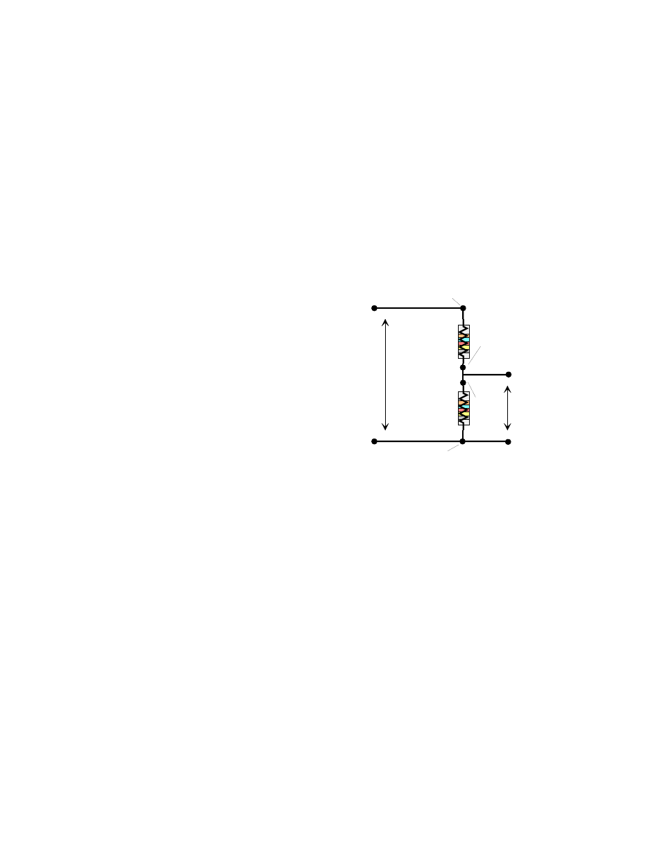
Volts In
Volts Divided
R11
R12
RES IN
RES
IN
RES OUT
RES
OUT
INPUT
PC GROUND
OUT
PC GROUND
4.3 Matching the schematic to
the board.
Figure 4-1 shows a voltage divider circuit
as it appears on the board. Refer to this
diagram, the board layout on Figure 4-2,
and sheet 1 of following schematics.
In the block labeled RESISTIVE
DIVIDERS, there are 2 circuits, A and B.
Circuit A is composed of resistors R11
and R12.
Figure 4-1. Voltage Divider Circuit
The two parallel rows of sockets appear on the schematic exactly as they are on the board. The
names of the signals are also exactly as they are written on the board. The pin labeled INPUT is
the high side (+) of the voltage to be divided. The pin labeled OUT is the high side of the
divided signal. Connect it to the A/D input.
The low sides of the voltage-in and voltage-out are connected to PC bus-ground on the board
and require no further connection.
Insert the divider resistors for input voltage in the sockets labeled RES IN for R11 and RES OUT
for R12.
The remainder of the circuitry is self-explanatory. For more information on resistor voltage
dividers please refer to any introductory electronics text.
The other circuits on the board are similarly shown on the schematic, and labeled on the board.
In all cases, where a circuit is shown connected to ground, the ground is PC chassis ground.
3