Cabling, Field wiring, signal termination, and conditioning – Measurement Computing CIO-DDA06/Jr/16 User Manual
Page 13
CIO-DDA06/Jr/16 User's Guide
Installing the CIO-DDA06/Jr/16
All the digital outputs inputs on the CIO-DDA06/Jr/16 connector are TTL level. Before connecting external
devices, review the specifications in this manual to avoid damage to the CIO-DDA06/Jr/16.
Cabling
20
1
37
19
20
1
37
19
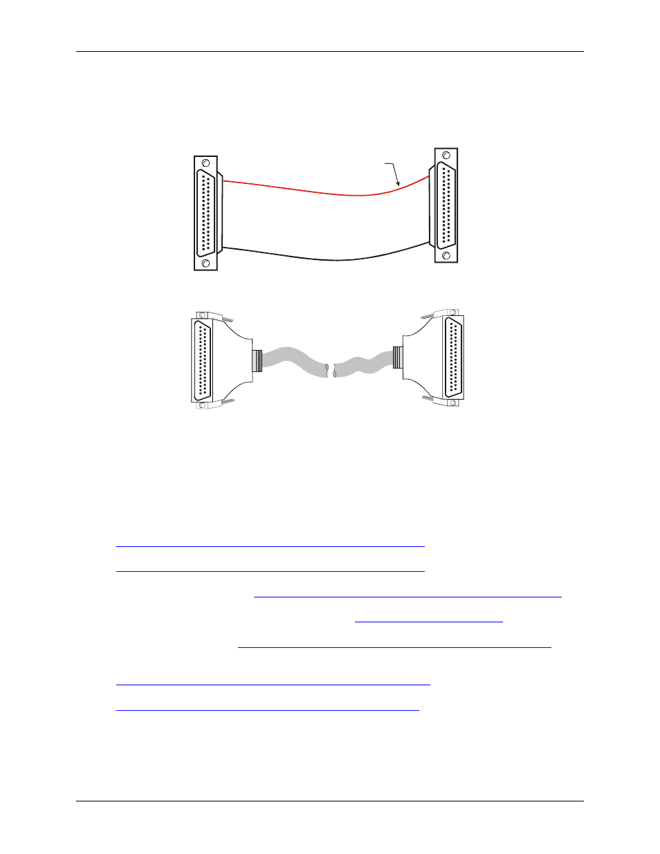
The red stripe
identifies pin # 1
Figure 5. C37FF-x cable
20
1
37
19
20
1
37
19
Figure 6. C37FFS-x cable
Field wiring, signal termination, and conditioning
You can use the following cabling, screw termination, and signal conditioning products with the CIO-
DDA06/Jr/16.
DFCON37 – Connector kit that includes a 37-pin female D-connector, D-shell, 37 crimp pins, and cable
termination kit to construct your own cable. Details on this product are available on our web site at
.
CIO-MINI37 – 37-pin screw terminal board. Details on this product are available at
.
CIO-TERMINAL – 37-pin screw terminal board with on-board prototyping area. Details on this product
are available on our web site at
CIO-SPADE50 — 16" X 4" termination panel which mates with both 37-pin and 50-pin connectors.
Details on this product are available on our web site at
SCB-37 – 37-conductor, shielded signal connection/screw terminal box. Details on this product are
available on our web site at
.
SSR-RACK24 – 24-channel, solid-state relay mounting rack for digital signal conditioning. Details on this
product are available on our web site at
ENC-MINI37– Enclosure for the MINI37. Details on this product are available at
.
13