Connecting the board for i/o operations, Connectors, cables – main i/o connector, Pinout – main i/o connector – Measurement Computing CIO-DDA06/Jr/16 User Manual
Page 12
CIO-DDA06/Jr/16 User's Guide
Installing the CIO-DDA06/Jr/16
Connecting the board for I/O operations
Connectors, cables – main I/O connector
The table below lists the board connector, applicable cables, and compatible accessory products.
Board connector, cables, and accessory equipment
Connector type
37-pin male "D" connector
Compatible cables
C37FF-x
C37FFS-x
DFCON-37 (D-connector, D-shell, and termination pins to construct your own cable)
Compatible accessory products
with the C37FF-x cable or
C37FFS-x cable
CIO-MINI37
CIO-TERMINAL
CIO-SPADE50
SCB-37
SSR-RACK24
ENC-MINI37
Information on signal connections
General information regarding signal connection and configuration is available in the Guide to Signal
Connections (available at
)
.
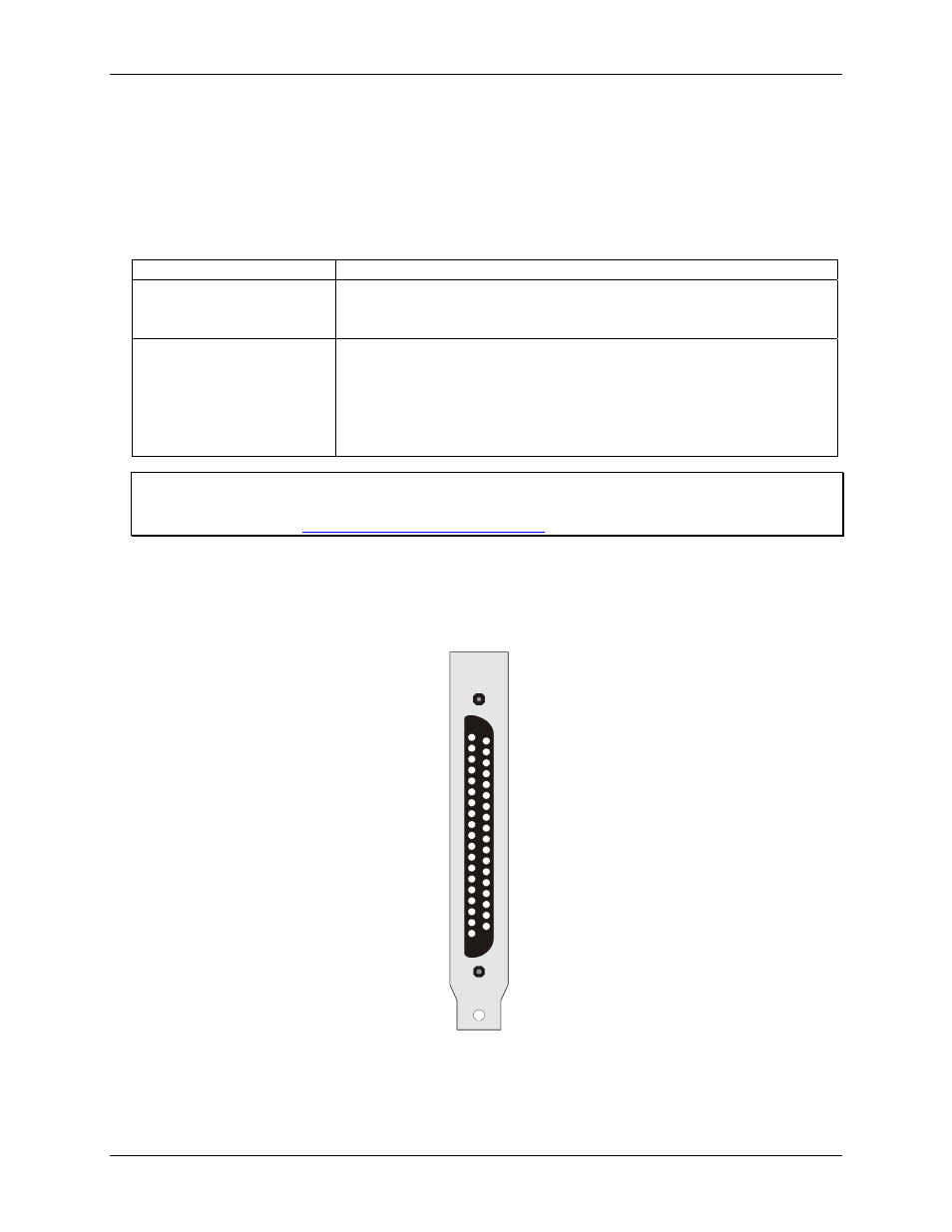
Pinout – main I/O connector
The CIO-DDA06/Jr/16 I/O connector is a standard 37-pin male connector that is accessible through the PC/AT
expansion bracket.
LLGND 19
D/A OUT 0 18
LLGND 17
16
LLGND 15
14
LLGND 13
12
DGND 11
FIRSTPORT B Bit 0 10
9
8
7
6
5
4
3
2
1
D/A OUT 1
D/A OUT 2
D/A OUT 3
FIRSTPORT B Bit 1
FIRSTPORT B Bit 2
FIRSTPORT B Bit 3
FIRSTPORT B Bit 4
FIRSTPORT B Bit 5
FIRSTPORT B Bit 6
FIRSTPORT B Bit 7
D/A OUT 4
D/A OUT 5
37
36
35
34
33
32
31
30
29
28
27
26
25
24
23
22
21 LLGND
20 LLGND
FIRSTPORT A Bit 0
FIRSTPORT A Bit 1
FIRSTPORT A Bit 2
FIRSTPORT A Bit 3
FIRSTPORT A Bit 4
FIRSTPORT A Bit 5
FIRSTPORT A Bit 6
FIRSTPORT A Bit 7
FIRSTPORT C Bit 0
FIRSTPORT C Bit 1
FIRSTPORT C Bit 2
FIRSTPORT C Bit 3
FIRSTPORT C Bit 4
FIRSTPORT C Bit 5
FIRSTPORT C Bit 6
FIRSTPORT C Bit 7
Figure 4. I/O connector pin-out
The analog outputs of the CIO-DDA06/Jr/16 are two-wire hook-ups. Always use low-level ground (LLGND)
as the ground reference for all analog hook-ups.
12