Installing the cio-das16/jr, Connecting the board for i/o operations, Connectors, cables – main i/o connector – Measurement Computing CIO-DAS16/Jr User Manual
Page 11: Pinout – main i/o connector
CIO-DAS16/Jr User's Guide
Installing the CIO-DAS16/Jr
Installing the CIO-DAS16/Jr
After configuring the board, install the CIO-DAS16/Jr into your computer. Follow the steps below.
Install the MCC DAQ software before you install your board
The driver needed to run your board is installed with the MCC DAQ software. Therefore, you need to install the
MCC DAQ software before you install your board. Refer to the Quick Start Guide for instructions on installing
the software.
1.
2.
3.
Turn your computer off, open it up, and insert your board into an available ISA slot.
Close your computer and turn it on.
To test your installation and configure your board, run the InstaCal utility you installed in the previous
section. Refer to the Quick Start Guide that came with your board
for information on how to initially set up and load InstaCal.
Connecting the board for I/O operations
Connectors, cables – main I/O connector
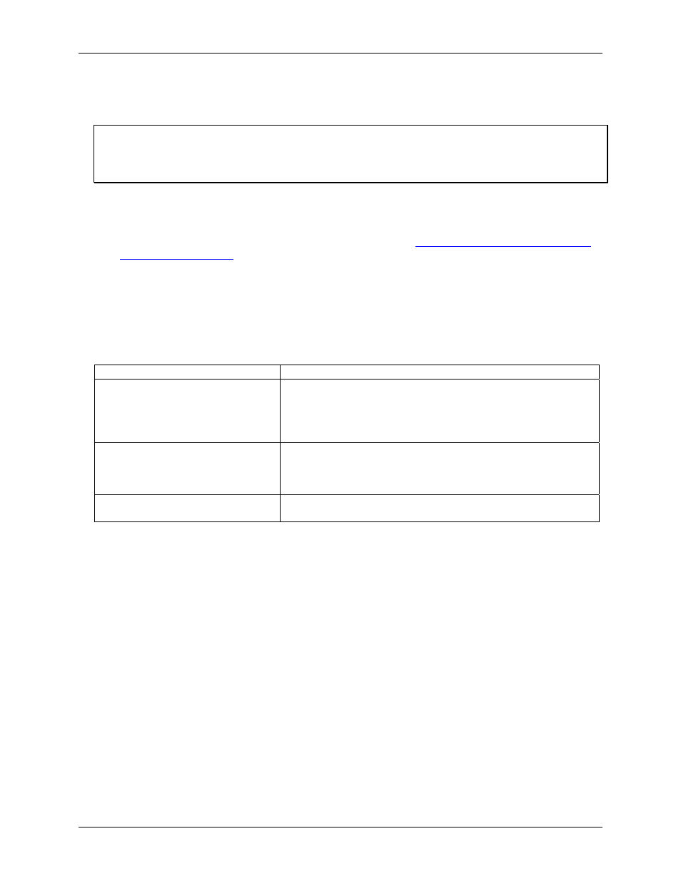
The table below lists the board connector, applicable cables, and compatible accessory products.
Board connector, cables, and accessory equipment
Connector type
37-pin male "D" connector
Compatible cables
C37FF-x
C37FFS-x
C-EXP2DAS16-10
DFCON-37 (D-connector, D-shell, and termination pins to construct your
own cable)
Compatible accessory products with the
C37FF-x cable or C37FFS-x cable
CIO-MINI37
CIO-TERMINAL
CIO-SSH16
ISO-RACK16
Compatible accessory products with the
C-EXP2DAS16-10 cable
CIO-EXP16
CIO-EXP32
Pinout – main I/O connector
The CIO-DAS16/Jr analog connector is a 37-pin D type connector accessible from the rear of the PC through
the expansion backplate (
). With the exception of the missing D/A signals, the signals available are
identical to the DAS-16.
11