Functional details, Cio-das-tc block diagram, Cio-sta-tc screw terminal adapter board – Measurement Computing CIO-DAS-TC User Manual
Page 12: Chapter 3, Isa bus
12
Chapter 3
Functional Details
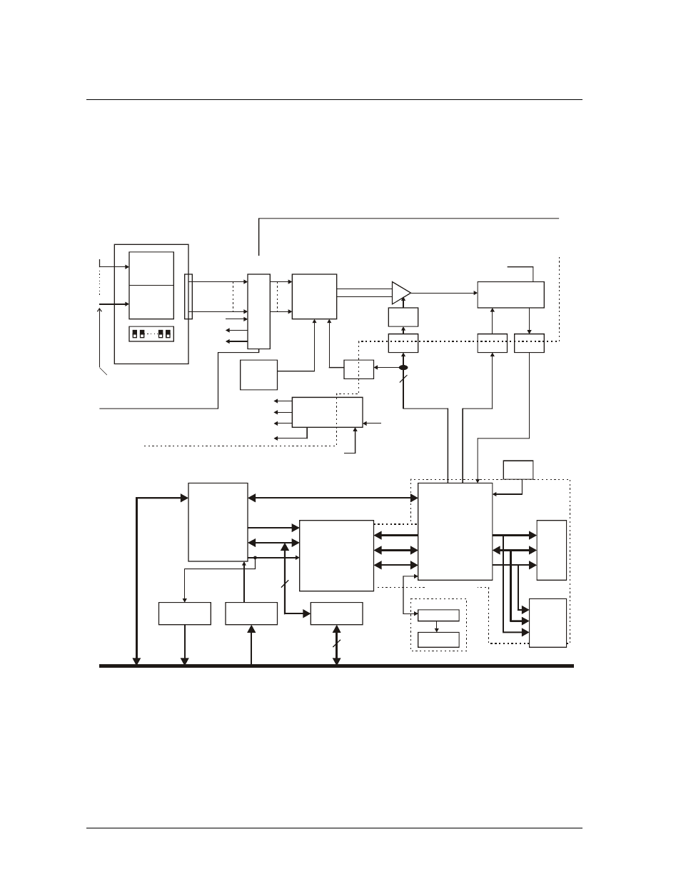
CIO-DAS-TC Block diagram
CIO-DAS-TC functions are illustrated in the block diagram shown here.
DUAL PORT
SRAM
AM188
CPU
Control
Logic
Control
Registers
Ser0
Interrupt
Decode
Address
Decode
Data Bus
Transceiver
SRAM
Flash
ROM
LOCAL BUS
DEBUG
PROGRAMMABLE
LOGIC
Control
Signals
Data
Control
Address
Data
Control
Board
Select
Processing and Control Section
‘232XCVR
10 PIN
Header
ISA BUS
IRQ2:7
A0:9
D0:7
Control
Data
Address
ISA
OSC
System +5
ISOLATION
BARRIER
7
DC/DC
Converter
OPTO
Isolator
Select:
CJC
Gain
Channel
Calibration
Fout
4MHz CLK
IN
V/F
Converter
+10V Ref
Gain
Mux
INA
20
Channel
Mux
37
Pin
+10V
Prec.
Ref
+5ISO
+15ISO
-15ISO
Input
Connector
+9.9V
8
8
Address
32MHz
OPTO
Isolator
OPTO
Isolator
OPTO
Isolator
Analog Ground
Digital
Ground
CIO-DAS-TC Board
Isolated Analog Input Section
CJC
AGND
TC Input
Channels
0 - 15
Screw
Terminal
CJC
Open Thermocouple
Detection Switches
0
15
External
CIO-STA-TC
Screw Terminal
+15ISO
Thermocouple
Input
Channels
Figure 4. CIO-DAS-TC block diagram
CIO-STA-TC screw terminal adapter board
The CIO-STA-TC is a specially configured screw terminal adapter board designed specifically for use
with the CIO-DAS-TC. The board has screw terminals for each thermocouple channel, a cold junction
sensor integrated into an isothermal bar, and the option of installing an "open thermocouple detection"
circuit.