Supplying power to ndtrelay2, Capacitor c7 and fuse locations – Measurement Computing NDTRELAY2 User Manual
Page 3
NDTRELAY2, Installation Guide
958596
3
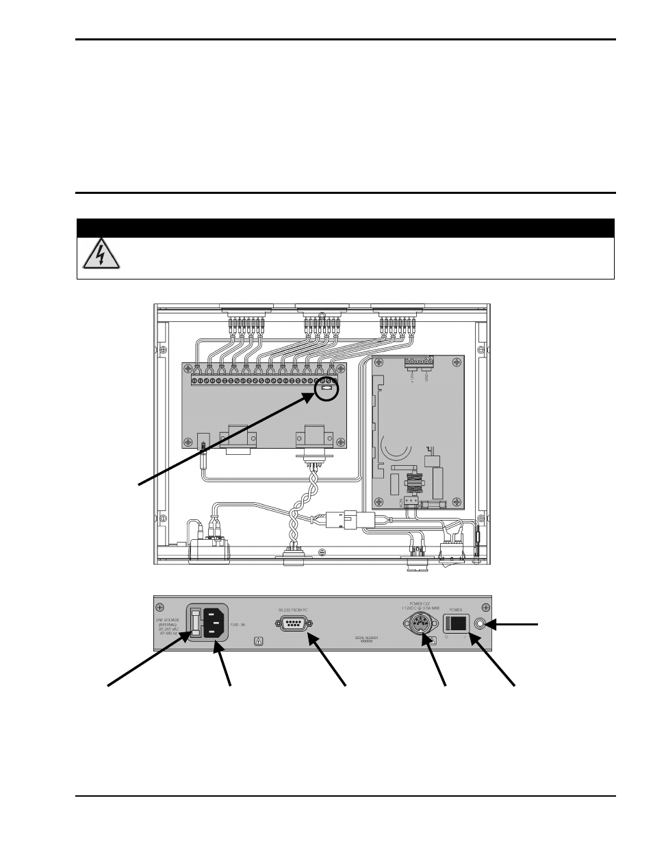
Supplying Power to NDTRELAY2
To supply power to the NDTRELAY2, plug the AC power cord into the unit’s Line Voltage Receptacle (see following
figure, lower image). Plug the other end of the cable into a suitable AC power outlet. Acceptable power is that which is in
the range of 85 VAC to 265 VAC, at 47 Hz to 440 Hz.
NDTRELAY2’s internal power supply converts the line voltage to +12 VDC. The DC power is made available to external
components through the DIN5 Power Out connector, located next to the Power Switch. You can power a ZonicBook from
this connector via a CA-115, DIN5 male to DIN5 male Power Cable. Note that an LED, located next to the Power Switch,
will light when the NDTRELAY2 is powered On (see following figure, lower image).
Capacitor C7 and Fuse Locations
WARNING
WARNING
WARNING
WARNING
Always turn OFF the NDTRELAY2 and unplug it before making or breaking any connections; or
before opening the unit for any reason. Failure to do so could result in electric shock, or equipment
damage.
Note 1: For dry Contact Type inputs, debounce capacitor C7 must be installed on the Relay Board. For TTL Type
inputs, C7 must be removed. Refer to Event Counter Connections, on page 2 of this document, for connection
drawings.
Capacitor C7
0.1 µf
(Note 1)
RELAY CARD
POWER
SUPPLY
PS-45-12
Fuse, 3 Amp Line Voltage Receptacle DB9S (Connects DIN5 Power Switch
to PC COM Port) (VDC Out)
Power LED