Connecting digital inputs and relay outputs – Measurement Computing NDTRELAY2 User Manual
Page 2
2
p/n
1099-0901,
rev
2.0
958596
NDTRELAY2, Installation Guide
Connecting Digital Inputs and Relay Outputs
WARNING
WARNING
WARNING
WARNING
Always turn OFF the NDTRELAY2 and unplug it before making or breaking any connections; or before
opening the unit for any reason. Failure to do so could result in electric shock, or equipment damage.
Digital Connections
Relay Output Connections
The four Digital Inputs have built-in weak pull-up resistors to
allow direct connection of dry contact inputs. These inputs
can be from any source, including switches and relays. TTL
signal sources [including TTL or NPN type proximity sensors]
can also be directly connected to Digital Input connections 0,
1, 2, or 3.
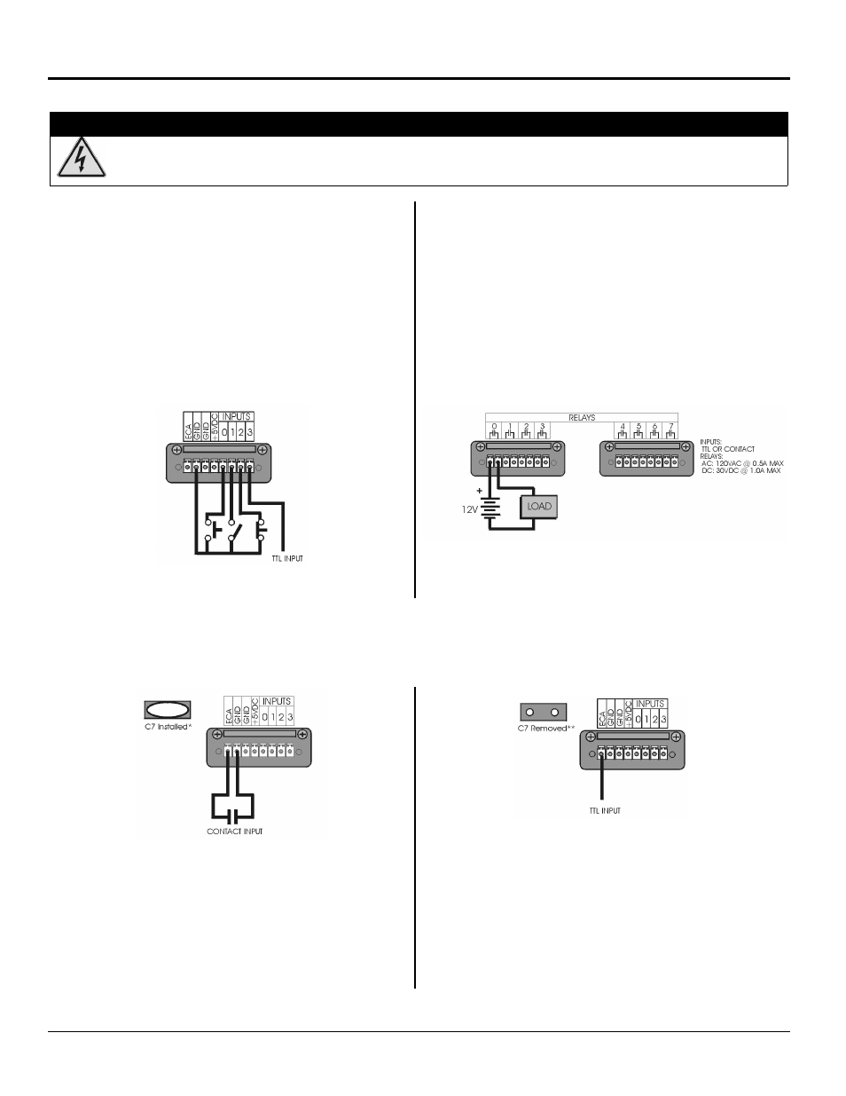
A typical Digital Input connection setup is represented by the
following figure. Notice that the contacts (switches) for
channels 0, 1, and 2 share a common ground. The digital TTL
input is not connected to ground.
NDTRELAY2 has eight normally open relay outputs labeled 0
through 7. The relays are capable of switching AC or DC loads,
as follows: up to 1 amp at 30 VDC; up to 0.5 amp at 120 VAC.
A typical connection, for Relay 0, is represented in the
following figure.
A Typical Setup for Digital Input
Typical Connection Shown for Relay 0
Event Counter Connections
The Event Counter can be configured to accept TTL or dry Contact Inputs. Connections for each are represented by the
following figures. Events are counted on the rising edge of the input, at which point the TTL signal switches from low to
high, or the dry contact opens.
Connecting a Contact Type Input
Connecting a TTL Type Input
Dry Contact Type inputs must be connected between Ground
and the ECA Input connection.
* For dry Contact Type inputs, debounce capacitor C7 must be
installed on the Relay Board. See the following figure for
location. By default, C7 is installed when the NDTRELAY2
is shipped.
TTL Type inputs are connected directly to the ECA contact.
** For TTL Type inputs, debounce capacitor C7 must be
removed. See the following figure for location.