Dbk34 operation, Connection, Caution – Measurement Computing DBK34 User Manual
Page 3
Connection
Power In - (vehicle main/auxiliary batteries, 12 or 24 VDC only) Connect main battery positive to
terminal 3 of TB1 and main negative to terminal 4. If an auxiliary battery is used, connect its positive to
terminal 1 and negative to terminal 2.
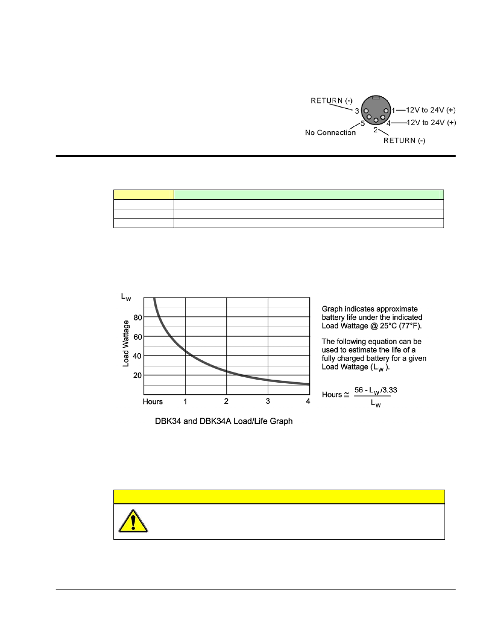
Power Out - The pinout at the right applies to DBK34’s
two POWER OUT DIN5 connectors.
DBK34 Operation
Indicators: 3 LEDs on the DBK34 provide status information on the power and charging process.
LED
Meaning
MAIN POWER
Lights when the DBK34 is connected to a live vehicle (main) battery.
CHARGING
Lights when internal batteries are being charged at a rate of 0.025 to 0.050 A or greater.
DISCHARGING
Lights when internal batteries are discharging at a rate of 0.025 to 0.050 A or greater.
Runtime: Approximate runtime under various loads can be computed from the storage capacity
(5 A-hr in 12 V mode; 2.5 A-hr in 24 V mode) and the load (main unit and other DBKs).
The following graph of Load vs. Battery Life is for a typical new battery that is initially at full charge.
Charging: In general, lead-acid batteries require charging at 120% of drain energy (e.g., the 5 A-hr
DBK34 requires a charge equal to or greater than 6 A-hr). Charging times vary; but 4 to 5 hours at 14 V
are typical for a totally empty battery.
CAUTION
Voltage applied to charge a DBK34 must not exceed 15 VDC in 12 V mode, or
30 VDC in 24 V mode. If not charging from the vehicle, use of a generic automobile
battery charger (3 A) in 12 V mode is recommended.
DBK Option Cards and Modules
879795
DBK34, pg. 3