Hardware setup – Measurement Computing DBK34 User Manual
Page 2
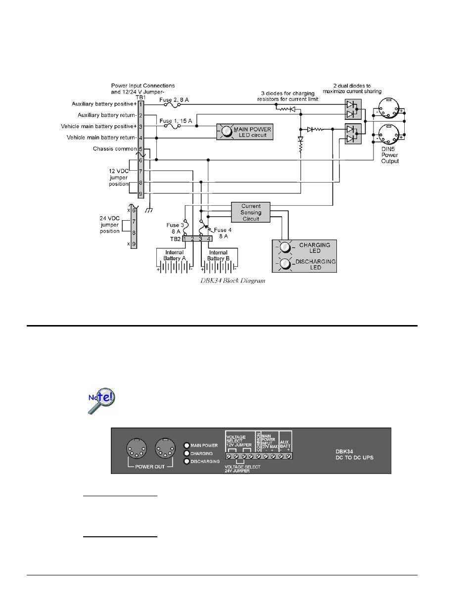
Main and auxiliary power input comes from 12 or 24 VDC via a terminal block on the unit’s front panel
(12 or 24 V modes are set by front-panel jumpers). Automatic charging circuits recharge the internal
batteries quickly and safely. For trouble-free operation, you must fully charge the batteries before use.
The charged battery runtime will depend on the load and mode of operation.
Note: TB1 pin numbers read from right to left as viewed from the front panel.
Hardware Setup
Configuration
The DBK34 is configured for 12 volt or 24 volt operation via placement of jumpers on the front panel’s
screw-terminal block (TB1).
From left to right, when viewed from the front panel, DBK34’s screw-terminal numbers
read: 9, 8, 7, 6, 5, 4, 3, 2, 1. Thus, Aux Batt (+) is screw –terminal 1. See following
figure.
For 12 Volt Operation:
(1) Remove jumper from terminals 8 and 7, if present.
(2) Use a jumper to short terminals 9 and 8
(3) Use a jumper to short terminals 7 and 6
For 24 Volt Operation:
(1) Remove jumpers from terminals 9 and 8, if present
(2) Remove jumpers from terminals 7 and 6, if present.
(3) Use a jumper to short terminals 8 and 7
DBK34, pg. 2
879795
DBK Option Cards and Modules