Measurement Computing DBK80 User Manual
Page 5
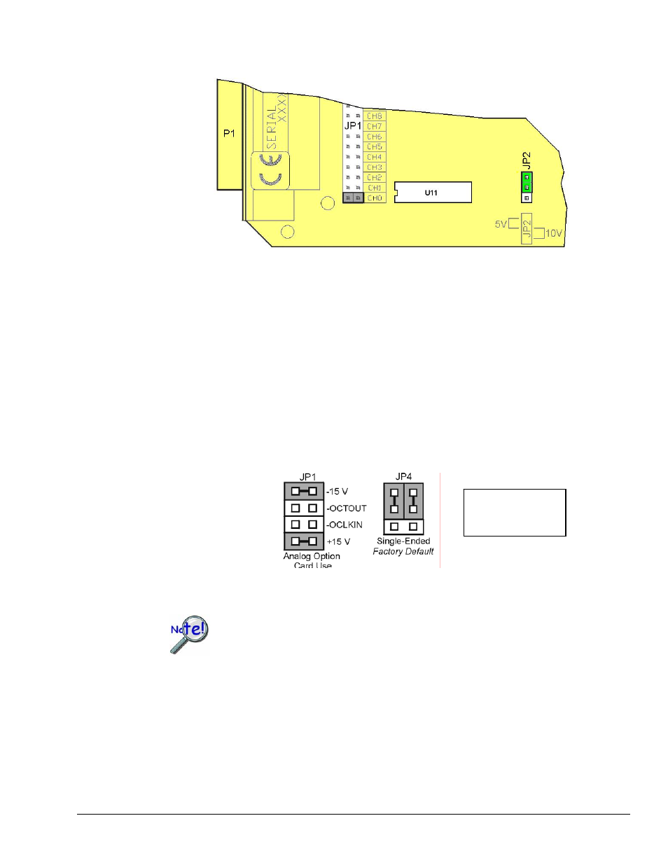
The excitation output voltage is set via JP2.
JP2 Location Reference
The above figure is of a partial DBK80. JP2 is shown selected to +5VDC. Note that the card’s overlay for
JP2’s voltage selection, also depicted in the figure, indicates the jumper positions that are required to select
the +5 or +10 VDC excitation output.
DaqBook/100 Series & /200 Series and DaqBoard [ISA type] Configuration
Use of a DBK80 with a DaqBook/100 Series & /200 Series devices, or with an ISA-type DaqBoard,
requires the configuration of jumpers JP1 and JP4 located on the DaqBook/100 Series & /200 Series
devices, or DaqBoard [ISA type], as applicable.
1. If not using auxiliary power, set the JP1 jumper for Analog Option Card Use,
also referred to as the expanded analog mode.
Note:
These jumpers do not
apply to /2000 Series
Devices.
Required Jumper Settings in DaqBook/100 Series & /200 Series
and ISA-Type DaqBoards
The JP1 default position (above) is necessary to power the interface circuitry of the
DBK80 via the internal ±15 VDC power supply. If using auxiliary power (e.g.,
DBK32A or DBK33) you must remove both JP1 jumpers.
Refer to Power Requirements in the DBK Basics section and to the DBK32A and
DBK33 sections for more detailed information, as applicable.
2. For DaqBook/100, DaqBook /112, and DaqBook /120 only, place the JP4 jumper in the single-ended
mode.
Note: Analog expansion cards convert all input signals to single-ended voltages that are referenced to
analog common.
DBK Option Cards and Modules
989494
DBK80 pg. 5