Hardware setup …… 2, Card connection …… 2, Hardware setup – Measurement Computing DBK80 User Manual
Page 2: Card connection, Caution
Hardware Setup
Card Connection
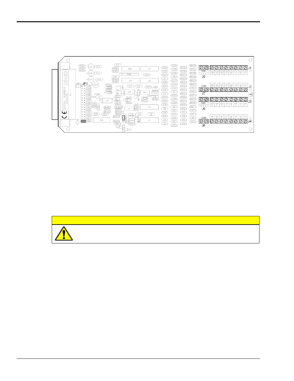
DBK80 Board Layout
Referring to the figure above, voltage input signals are connected to the screw terminal blocks labeled J1,
J2, J3, and J4. Each channel is labeled with “H” and “L” to denote its polarity. These inputs accept
voltages up to
±10 VDC.
Excitation Source
J5 and J6 provide the excitation source output, again labeled with “H” and “L” to denote polarity. Note
that J5 and J6 are connected in parallel. There is only one voltage source; two connectors are simply
provided for wiring convenience.
The excitation source is ground-referenced, not floating. That is, its low terminal is connected to the
ground of the Daq device. It is designed to interface to circuits where it is the only power source, or where
its connection is electrically isolated from other power sources. An example of the latter is an optocoupler.
CAUTION
Do not connect the excitation source to a non-isolated, powered circuit. Making such a
connection can cause damage to both the DBK80 and to the circuit under test.
The excitation source outputs should also be used together, with the “L” of the source providing the ground
reference to the connecting circuit. This provides two benefits. It maintains the accuracy of the source,
since the regulation of the “H” terminal is referenced to the “L” terminal. It also returns the load current
directly to its source, where its path is designed to not influence any other part of the measurement system.
DBK80 pg. 2
989494
DBK Option Cards and Modules