Measurement Computing DBK60 User Manual
Page 5
7 – Install a power card, if needed
If you determined [in step 5] that additional power is needed, add a DBK32A or DBK33 power card to the
acquisition processor chassis, or to the DBK60 expansion chassis.
To install a power card in a DBK60 complete steps 7A and 7B. Refer to the previous figure as needed.
A. Carefully align the power card’s DB37 connector with a DB37 connector on DBK60’s P1 interconnect
board and gently press the power card to establish a complete and solid connection.
B. Use two screws to secure the power card to DBK60’s card drawer standoffs.
8 – Configure the DBK cards
Configure channel addresses that are unique to each card; i.e., do not duplicate addresses. Some cards make
use of jumpers for address configuration, while others make use of DIP switches.
Reference Note:
Refer to the appropriate DBK document modules in regard to specific DBK configuration.
9 – Install the DBK cards
You cannot mix analog and digital DBK cards in the DBK60; in other words, use all analog or
all digital, but not both.
A. Carefully align the DBK card’s DB37 connector with a DB37 connector on the interconnect board and
gently press gently press the DBK card to establish a complete and solid connection (see previous figure).
B. Use two screws to secure the DBK card to the standoffs on the DBK60 card drawer (see previous figure).
C. Repeat installation steps 9A and 9B for additional DBK cards, as applicable. Be sure that all cards to be
installed are analog, or all digital. Analog and digital can not be mixed within a DBK60.
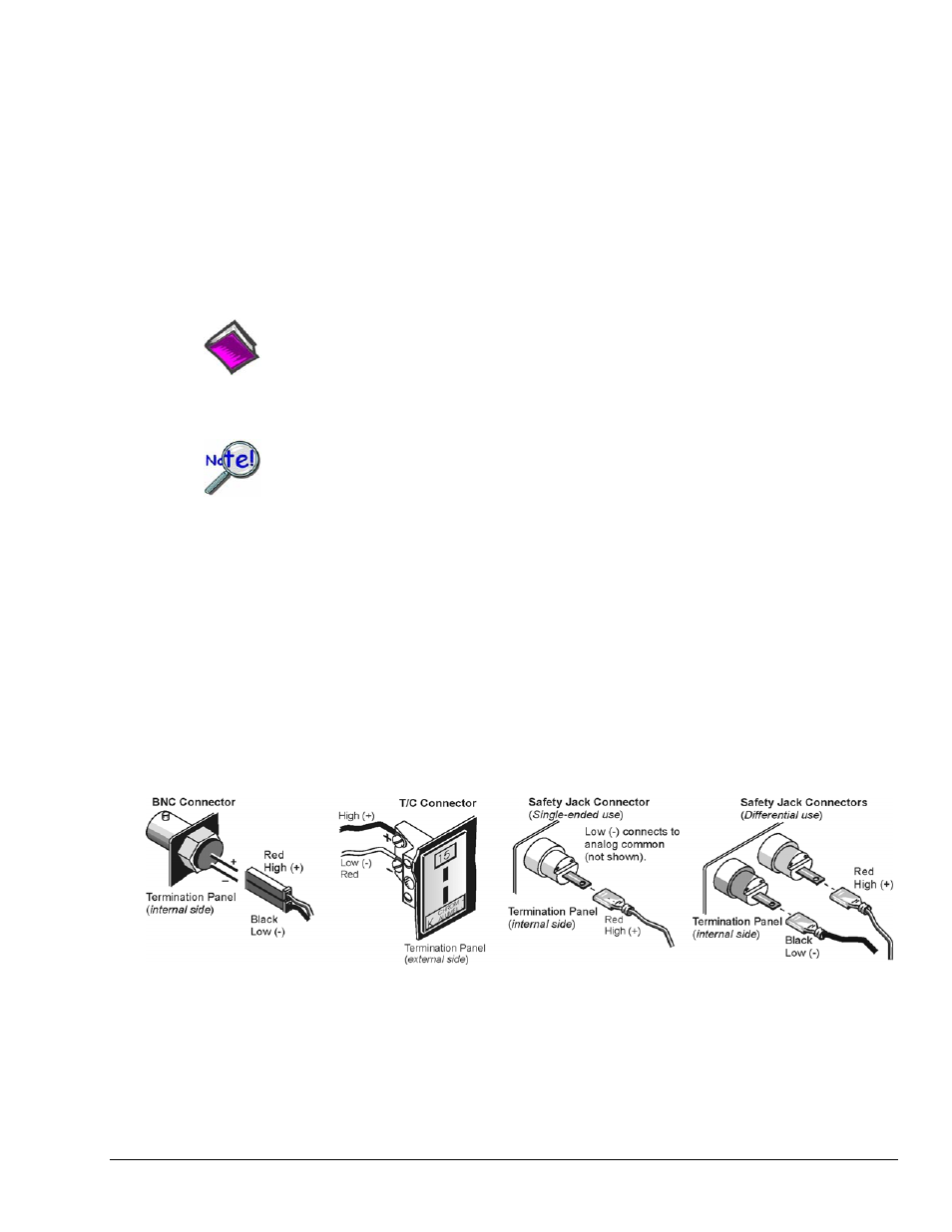
10 – Connect the internal signals
Connect signal inputs from DBK cards to the termination panels. DBK cards connect to the termination
panels in various ways. Refer to the following figure and to the specific DBK document modules as needed.
• Single-ended connections use analog common.
• Differential connections require the proper polarity, typically red-to-red for high (+) and
black-to-black for low (-).
• For thermocouples, red is generally the low side. The T/C connector and wire type must match the T/C
type used.
11 – Install the termination panels
Mount the termination panels to the card drawer. Use two screws to secure each panel.
Refer to the DBK60 Hardware Setup figure.
DBK Option Cards and Modules
989594
DBK60, pg. 5