6 – configure the chassis for the power source – Measurement Computing DBK60 User Manual
Page 4
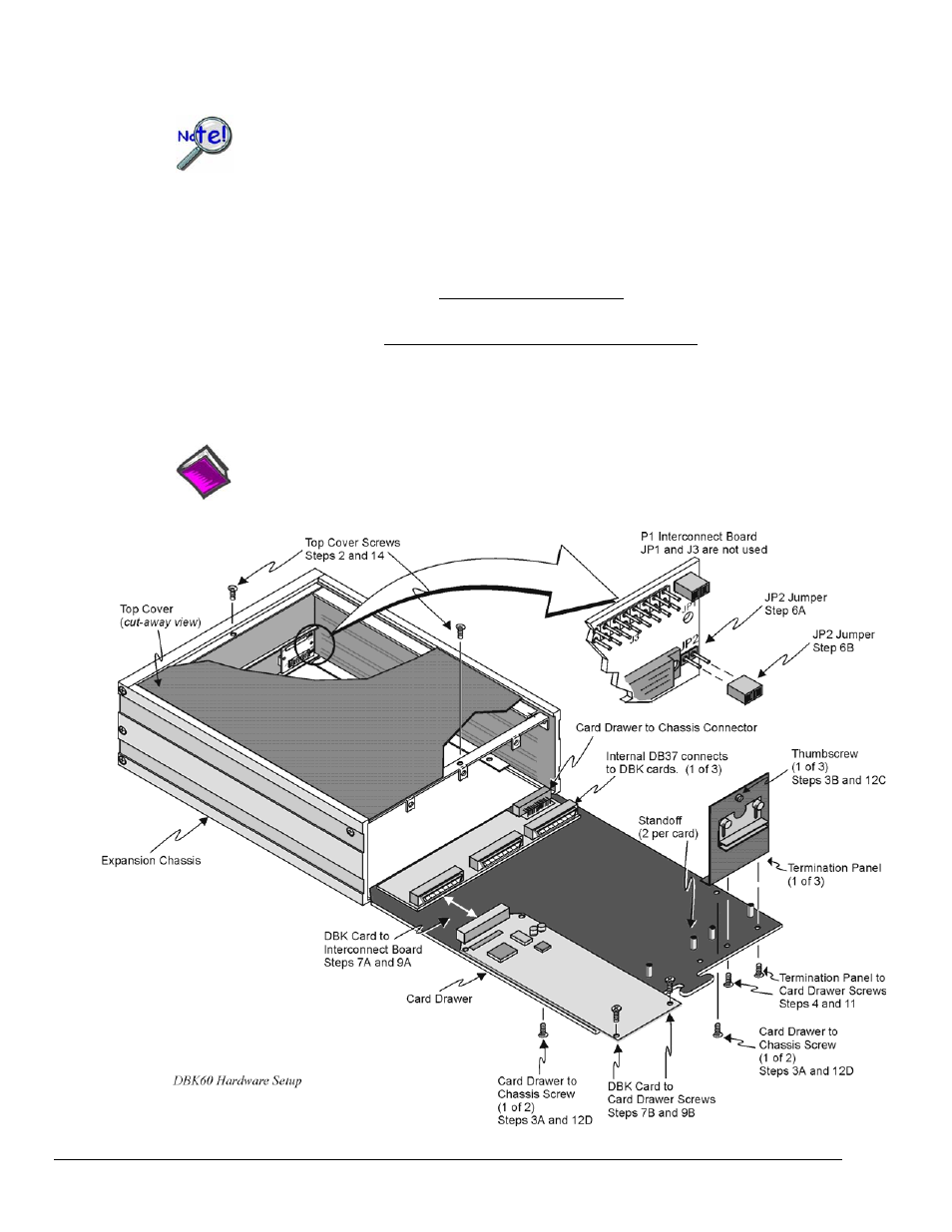
6 – Configure the chassis for the power source
Use one power source, and only one power source, for cards on the P1 bus!
+5 V is selected with the DBK60’s JP2 jumper, located inside the expansion chassis on the P1
interconnect board (see the following figure for location).
±15 V is selected with two JP1 jumpers, located on the board of the primary data
acquisition device, such as a DaqBook or ISA-type DaqBoard.
DO NOT CONFUSE THESE JP1 JUMPERS WITH THE JP1 JUMPER IN THE DBK60.
A. If +5 V will be supplied from a source outside the expansion chassis, place a jumper on DBK60’s JP2
header. JP2 is located on the P1 interconnect board (see figure).
B. If +5 V will be supplied from a DBK33 power card inside the expansion chassis, remove the jumper
from the JP2 header (located on the P1 interconnect board).
C. If using a DBK32A or DBK33 power card anywhere in the system, remove the +15 V and -15 V
jumpers from JP1 on the primary data acquisition device, such as a DaqBook or ISA-type
DaqBoard.
DO NOT CONFUSE THESE JP1 JUMPERS WITH THE JP1 JUMPER IN THE DBK60.
Reference Notes:
Refer to the DBK32A or DBK33 sections, if applicable.
DBK60, pg. 4
989594
DBK Option Cards and Modules