Card insertion – Measurement Computing DBK41 User Manual
Page 3
JP1 and JP2 in LogBook/360
Proper jumper configuration limits LogBook/360’s P1 bus to one power source. There should never be
more than one power source. The jumpers are located inside the chassis, on the unit’s P1 Interconnect
Board.
JP1.
Only remove LogBook/360’s JP1 jumper if a DBK33 is used with the system.
JP2.
Only remove the LogBook/360’s JP2 jumper if DBK cards are to be powered from LogBook/360’s
internal PCB.
Reference Note:
Refer to the LogBook User’s Manual, 461-0901 for information regarding LogBook systems.
DaqBook/2000 Series & DaqBoard/2000 Series Configuration
No jumper configurations are required for these /2000 series devices.
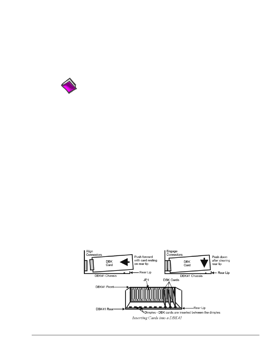
Card Insertion
Each DBK card has a DB37 male connector which mates with the DB37 female connectors inside the
DBK41 chassis. To insert DBK cards into the DBK41 chassis, refer to the figure and perform the
following steps.
Note: Cards using screw-connectors for signal input lines must be wired before insertion.
1. Disconnect power from all units to be connected.
2. Place the DBK41 on a flat surface; loosen the two thumbscrews on rear of the case; and remove the
top cover by sliding it off.
3. Align the DBK card with the DBK41 connector to be used (CN1 to CN10). The first slot must always
be occupied; however, a DBK32A or DBK33 power card may not occupy the first slot. Any of the
remaining 9 slots can be used or unused.
4. To clear the lip on the rear panel, tilt the rear of the card upward. Engage the P1 connectors of the
card and chassis, and press together gently to avoid damage to the pins.
5. Press down the rear of the card, aligning it within the metal dimples at the rear of the DBK41.
6. After cards are in place, reassemble the DBK41’s top cover and attach optional shield plates
(described next); then re-connect and power up the system.
DBK Option Cards and Modules
877095
DBK41, pg. 3