Hardware setup – Measurement Computing DBK41 User Manual
Page 2
Hardware Setup
Setup concerns include card and power configuration, proper card insertion, the use of EMI shields for CE
compliance, and mounting [or stacking] of hardware components.
In regard to mounting: metal splice plates can be used to rigidly mount a LogBook or DaqBook on top of a
DBK41 or other device that shares the same footprint. For applications in which temporary mounting is
convenient: a LogBook, DaqBook or notebook PC can be temporarily mounted to a DBK41 with the use
of industrial-strength dual-lock pads or strips.
Card Configuration
Each DBK card should be checked for proper configuration, and re-configured if needed, before being
inserted into the DBK41. Refer to the individual DBK Document Modules that are applicable to your
system.
Power Configuration
Power must be configured to prevent multiple power supplies from interfering with each other via the P1
interface. DBK41, LogBook/360, DaqBook/100 Series & /200 Series, and ISA-type DaqBoard each have
JP1 jumpers that must be properly configured in regard to power. Details for each follow.
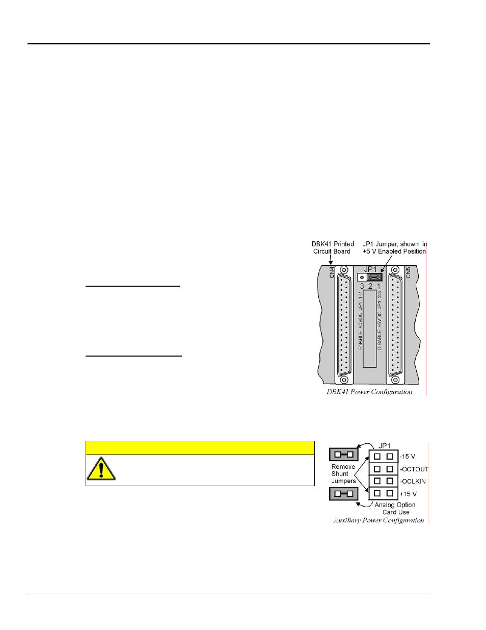
JP1 in the DBK41
On the DBK41 backplane, JP1 is a 3-pin jumper positioned between
DB37 connectors for card number 4 (CN4) and card number 5
(CN5). Two settings are possible, as follows:
ENABLE +5 VDC JP1 1-2
When JP1 pins 1 and 2 are jumpered, the +5 VDC line to the
external P1 connector is enabled. The 5 V (VCC) is externally
supplied to pin 1 for cards 1 through 10 (CN1 through CN10). The
+5 VDC power can come from a LogBook, DaqBook, or DaqBoard
through a CA-37-x cable on pin 1 of P1. If not using a DBK33, JP1
should be enabled.
DISABLE +5 VDC JP1 2-3
When JP1 pins 2 and 3 are jumpered, the +5 VDC line to the
external P1 connector is disabled. When using a DBK33 power
card in the DBK41, the JP1 jumper must be set on pin 2 and 3. The
JP1 2-3 setting prevents the DBK33’s +5 V from interfering with
external devices via the P1 interface.
JP1 in the DaqBook/100 Series & /200 Series and DaqBoard [ISA type]
CAUTION
DBK power cards must not be connected until JP1
jumpers have been removed. Otherwise, equipment
damage could result.
If a DBK32A or DBK33 is used, you must remove the shunt jumpers
from the JP1 header located inside the DaqBook/100 Series & /200 Series
device or DaqBoard [ISA type]. DaqBook/100 Series & /200 Series
devices and DaqBoards [ISA type] are shipped with these shunts
positioned to deliver ±15 V analog power to P1.
Note: The jumpers can be placed on the -OCTOUT and -OCLKIN pins but should be removed if there is
interference with card operation (counter-timer).
DBK41, pg. 2
877095
DBK Option Cards and Modules