Measurement Computing DBK210 User Manual
Page 8
DBK210, pg. 8
987594
DBK Option Cards and Modules
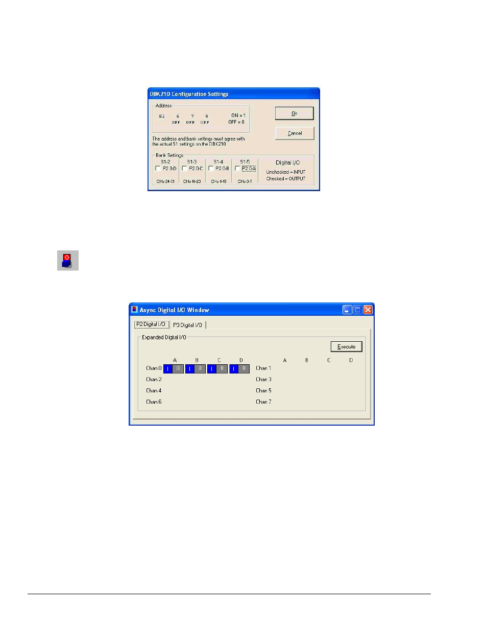
5. Set S1 micro-switches to agree with the actual settings of the switches on the DBK210 boards. Use
“OFF” to obtain a setting of “0” for each switch and use “ON” to obtain a setting of “1.” A detailed
explanation of address settings is provided on 6.
DBK210 Configuration Settings
6. Independently set the four banks P20-A, P20-B, P20-C, and P20-D. A checked box indicates that the
associated bank is Digital Output. An unchecked box indicates Digital Input.
7. After S1 and the bank Input / Output settings are complete, click the
8. Select the Digital I/O icon from DaqView’s main window toolbar. The Async Digital I/O window will
appear (following figure).
With the P2 Digital I/O tab selected in the Async Digital I/O window, each active channel has
divisions for the four banks (A, B, C, and D).
Async Digital I/O Window – P2 Digital I/O Tab Selected
In the above screen shot, channel 0 represents one DBK210 board with its four banks: A, B, C, and D.
In this example all four banks are seen as Input. The input determination was made by the physical
positions of micro-switches 2, 3, 4, and 5 on switch S1. Because the 4 banks are set as input, the
DBK210 Configuration Settings dialog box shows the Input / Output boxes as “unchecked.”
When Output is selected, hexadecimal values must be entered in the “O” block for the applicable bank.
9. Upon completion of the configuration click the