Pg. 5), Pg. 5), and, Power – Measurement Computing DBK210 User Manual
Page 5: External power watchdog, Setting module banks to input or output
Power
The DBK210 requires an external isolated 5 volt DC power
supply with at least 0.600 amp current capacity. External power
attaches to the DBK210 via on-board screw terminal connections.
The board contains capacitors to filter input noise from the power
supply.
Over-current protection is provided by an on-board 3.0 amp
resettable fuse (F32), which is in series with the 5 volt supply.
Protection from over-voltage and reverse polarity power
conditions is provided by a 6.8V zener diode (D32).
Connecting an External 5 VDC Supply
External Power Watchdog
Set via S1, Switch 1
The External Power Watchdog is governed by the position of
micro-switch 1 on switch S1. The feature allows the user to set
the desired behavior of the digital output latches in the event of a
loss and recovery of the external power supply.
With micro-switch 1 in the Enable position, a loss of external
power will cause the output latches to be reset into a high-
impedance condition. Even with a recovery of the external
power, all output modules will be disabled until a write is done to
the data bus. This setting is useful in an application that requires
a serial enabling of output loads.
With micro-switch 1 in the Disable position, a loss of external power will have no effect on the state or
continued control of the output latches. That is, data that is written to the output modules will continue to
be latched as normal. A recovery of the external power would then cause the output modules to reflect the
current state of the output latches. This setting is useful in the case where the operator halts the transfer of
data and turns off the external power on purpose and then wants the system to assume the same state upon
recovery of the external power.
The position of micro-switch 1 has no effect on input modules in regard to external power. While a loss of
external power will result in corruption of the data being read, the data bus will be valid again immediately
upon the recovery of the external power.
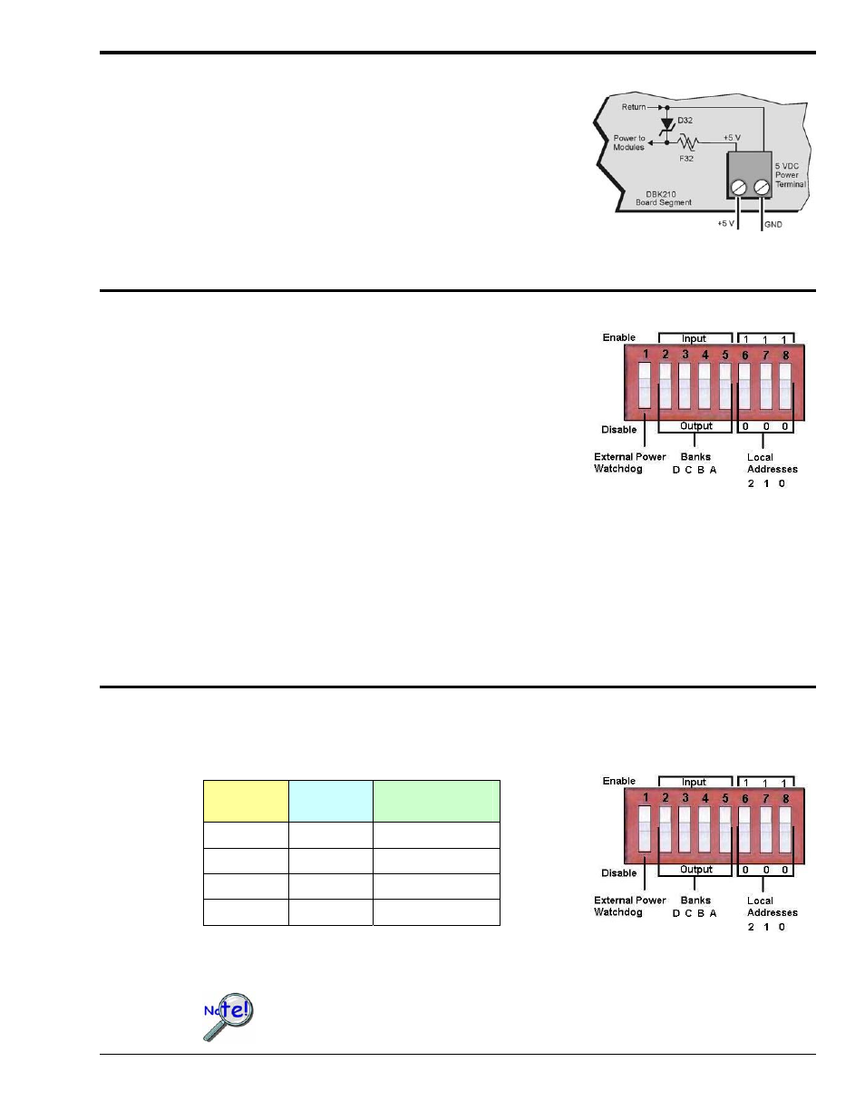
Setting Module Banks to Input or Output
Set via S1, Switches 2, 3, 4, & 5
Four of the S1 micro-switches (2, 3, 4, and 5) are used to individually set the digital I/O module banks to
input or output mode. The following table indicates the associations between the micro-switches, banks,
and channels.
Micro-
Switch
Affected
Bank
Affected
Channels
2
D
24 thru 31
3
C
16 thru 23
4
B
8 thru 15
5
A
0 thru 7
All eight channels for a given bank must be of the same type, i.e., digital input or digital output. However,
the banks themselves can be set to input or output, regardless of how the other banks are set. For example,
Bank A could be set to digital input and banks B, C, and D could be set to digital output.
The S1 settings for the Banks must match the associated settings in DaqView.
This is explained in the Software Setup section, which begins on page 7.
DBK Option Cards and Modules
987594
DBK210, pg. 5