External components, Screw terminals, Usb connector – Measurement Computing USB-TC-AI User Manual
Page 14: Leds, Power
USB-TC-AI User's Guide
Functional Details
14
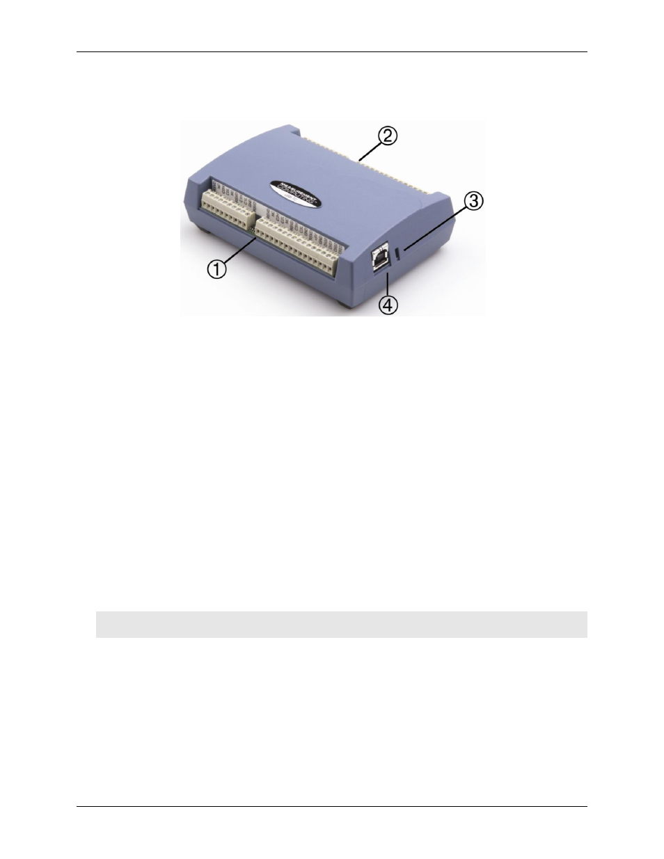
External components
The USB-TC-AI has the following external components, as shown in Figure 5.
1
Screw terminal pins 1 to 26
3
LEDs: Activity (top) and Power (bottom)
2
Screw terminal pins 27 to 52
4
USB connector
Figure 5.External component locations
Screw terminals
The screw terminals provide connections for thermocouples, voltage input, digital I/O, ground and power
output. Refer to the "Signal I/O ConnectionsError! Reference source not found." chapter beginning on page
10 for screw terminal descriptions.
USB connector
The USB connector provides +5V power and communication. No external power supply is required.
LEDs
USB-TC-AI has two LEDs –
Activity
and
Power
.
The
Activity
LED (top) blinks when data is transferred.
The
Power
LED (bottom) turns on when the device is receiving power from the USB cable .
Power
The two
+5V
terminals are isolated (500 VDC) from the USB +5V.
Caution! Each +5V terminal is an output. Do not connect to an external power supply or you may damage
the USB-TC-AI and possibly the computer.