Signal i/o connections, Screw terminal pinout, Voltage input – Measurement Computing USB-TC-AI User Manual
Page 10
10
Chapter 3
Signal I/O Connections
Screw terminal pinout
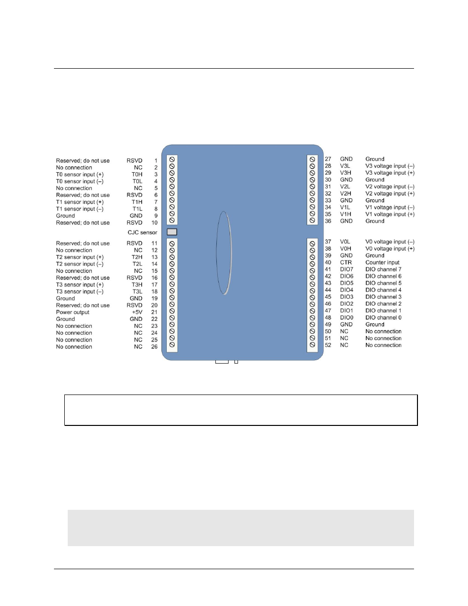
The USB-TC-AI has four rows of screw terminals — two rows on the top edge of the housing, and two rows on
the bottom edge. Each row has 26 connections. Between screw terminals 10 and 11 is the integrated CJC sensor
used for thermocouple measurements. Signals are identified in Figure 2.
Figure 2. USB-TC-AI screw terminal pin numbers
Use 16 AWG to 30 AWG wire for your signal connections.
Tighten screw terminal connections
When making connections to the screw terminals, be sure to tighten the screw until tight. Simply touching the
top of the screw terminal is not sufficient to make a proper connection.
Voltage input
You can connect up to four voltage inputs to the voltage channels (
V0H
/
V0L
to
V3H
/
V3L
). The input range is
software programmable for ±10 V, ±5 V, ±2.5 V, or ±1.25 V. Each voltage channel is software configurable for
differential or single-ended mode.
When connecting differential inputs to floating input sources, you must provide a DC return path from each
differential input to ground. One way to do this is to connect a resistor from one side of each of the differential
inputs to GND. A value of approximately 100 kΩ can be used for most applications.
Caution! All ground pins on the USB-TC-AI (pins 9, 19, 22, 27, 30, 33, 36, 39, 49) are common and are
isolated from earth ground. If a connection is made to earth ground when using digital I/O and
conductive thermocouples, the thermocouples are no longer isolated. In this case, thermocouples
must not be connected to any conductive surfaces that may be referenced to earth ground.