Synchronous dac load, Counter – Measurement Computing USB-3101 User Manual
Page 20
USB-3101 User's Guide
Specifications
20
Note 4:
Pull up and pull down configuration area available using the DIO CTL terminal block pin 54.
The pull down configuration requires the DIO CTL pin (pin 54) to be connected to a DGND pin
(pin 50, 53 or 55). For a pull up configuration, the DIO CTL pin should be connected to the +5V
terminal pin (pin 56).
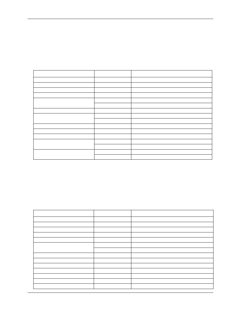
Synchronous DAC Load
Table 7. SYNCLD I/O specifications
Parameter
Conditions
Specification
Pin name
SYNCLD (terminal block pin 49)
Power on and reset state
Input
Pin type
Bidirectional
Termination
Internal 100K ohms pull-down
Software selectable direction
Output
Outputs internal D/A LOAD signal.
Input
Receives D/A LOAD signal from external source.
Input clock rate
100 Hz max
Clock pulse width
Input
1 µs min
Output
5 µs min
Input leakage current
±1.0 µA typ.
Input high voltage
4.0 V min, 5.5 V absolute max
Input low voltage
1.0 V max, –0.5 V absolute min
Output high voltage (Note 5)
IOH = –2.5 mA
3.3 V min
No load
3.8 V min
Output low voltage (Note 6)
IOL = 2.5 mA
1.1 V max
No load
0.6 V max
Note 5:
SYNCLD is a Schmitt trigger input and is over-current protected with a 200 Ohm series resistor.
Note 6:
When SYNCLD is in input mode, the analog outputs may either be updated immediately or when
a positive edge is seen on the SYNCLD pin (this is under software control.) However, the pin
must be at a low logic level in order for the DAC outputs to be updated immediately. If an
external source is pulling the pin high, no update will occur.
Counter
Table 8. CTR I/O specifications
Parameter
Conditions
Specification
Pin name
CTR
Number of channels
1
Resolution
32-bits
Counter type
Event counter
Input type
TTL, rising edge triggered
Counter read/writes rates
(software paced)
Counter read
System dependent, 33 to 1000 reads per second.
Counter write
System dependent, 33 to 1000 reads per second.
Schmidt trigger hysteresis
20 mV to 100 mV
Input leakage current
±1.0 µA typ.
Input frequency
1 MHz max.
High pulse width
500 nS min.
Low pulse width
500 ns min.
Input high voltage
4.0 V min, 5.5 V absolute max
Input low voltage
1.0 V max, –0.5 V absolute min