Introducing the usb-1208fs-plus-oem, Functional block diagram – Measurement Computing USB-1208FS-Plus-OEM User Manual
Page 6
6
Chapter 1
Introducing the USB-1208FS-Plus-OEM
The USB-1208FS-Plus-OEM is a USB 2.0 full-speed analog input and digital I/O data acquisition device that
provides the following features:
Eight analog input channels that are software-selectable for either eight 11-bit single-ended inputs or four
12-bit differential inputs
Two 12-bit analog output channels
16 digital I/O channels that are independently-selectable as input or output in two 8-bit ports
32-bit event counter input for counting TTL pulses
External digital trigger input
Bidirectional external clock for synchronous operation with more than one device.
Two header connectors for field wiring connections
The USB-1208FS-Plus-OEM device is compatible with both USB 1.1 and USB 2.0 ports. The speed of the
device may be limited when using a USB 1.1 port due to the difference in transfer rates on the USB 1.1 versions
of the protocol (low-speed and full-speed).
The device is powered by the +5 V USB supply from the computer. No external power is required.
Caution! There are no product safety, electromagnetic compatibility (EMC), or CE marking compliance
claims made for the USB-1208FS-Plus-OEM. The USB-1208FS-Plus-OEM is intended for use as
a component of a larger system. MCC can help developers meet their compliance requirements.
The end product supplier, however, is responsible for conforming to any and all compliance
requirements.
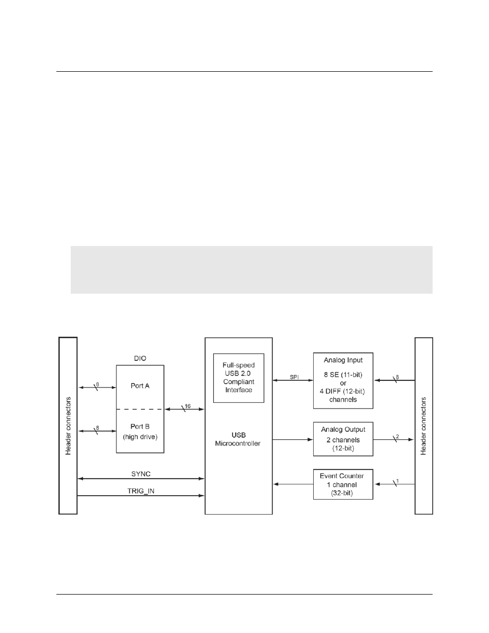
Functional block diagram
Device functions are illustrated in the block diagram shown here.
Figure 1. USB-1208FS-Plus-OEM functional block diagram