Wire the vis together, Run the vi – Measurement Computing ULx for NI LabVIEW Quick Start User Manual
Page 6
Quick Start: MCC ULx for NI LabVIEW
Run the VI
6
Wire the VIs together
1. Connect a wire between the
task out
terminal on one VI to the
task in
terminal on the adjacent VI.
2. Connect a wire between the
error out
terminal on one VI to the
error in
terminal on the adjacent VI.
3. Connect a wire between the Waveform Graph to the
data
terminal on the ULx Read.vi.
4. Connect a wire between the
signals
terminal on the Write to Measurement File VI to the
data
terminal on
the ULx Read VI.
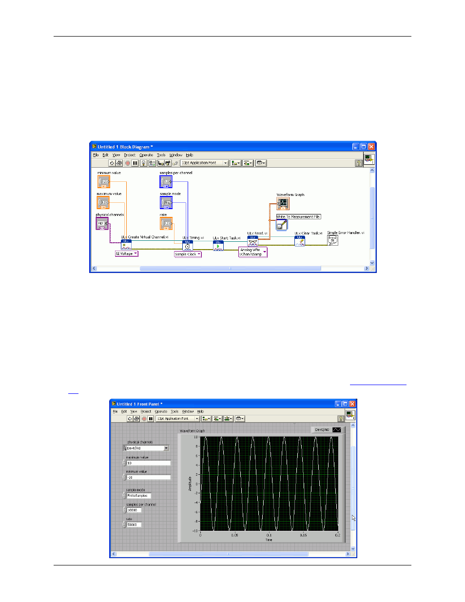
The block diagram should look like the diagram shown here:
Run the VI
After creating the source code for the program, display the front panel and configure the user interface.
Complete the following steps:
1. Click the
physical channels
arrow and select
Dev0/Ai0
to acquire data from channel 0 on device 0. The
device number is associated with the device installed in InstaCal as "Board# 0".
2. Set the voltage range, sample mode, samples per channel, and rate to values supported by your hardware.
The front panel shown below is configured with values supported by the USB-1608GX-2AO.
3. Click the
Run
button on the toolbar to run the VI.
Waveform data displays on the front panel, and the data is written to the file specified in the
procedure on page 5. Data acquired from the USB-1608GX-2AO is shown below.