Pinout – main i/o connectors, Cabling, Pinout – main i/o connectors -5 – Measurement Computing PCIM-DDA06/16 User Manual
Page 13: Cabling -5
PCIM-DDA06/16 User's Guide
Installing the PCIM-DDA06/16
Pinout – main I/O connectors
The PCIM-DDA06/16 I/O connector is a standard 37-pin male connector that is accessible through the PC/AT
expansion bracket.
1 D/A
OUT
5
2 D/A
OUT
4
3
FIRSTPORTB Bit 7
4
FIRSTPORTB Bit 6
5
FIRSTPORTB Bit 5
6
FIRSTPORTB Bit 4
7
FIRSTPORTB Bit 3
8
FIRSTPORTB Bit 2
9
FIRSTPORTB Bit 1
10 FIRSTPORTB Bit 0
11 DGND
12 D/A OUT 3
13 LLGND
14 D/A OUT 2
15 LLGND
16 D/A OUT 1
17 LLGND
18 D/A OUT 0
19 LLGND
LLGND
20
FIRSTPORTC Bit 7
22
FIRSTPORTC Bit 6
23
FIRSTPORTC Bit 5
24
FIRSTPORTC Bit 4
25
FIRSTPORTC Bit 3
26
FIRSTPORTC Bit 2
27
FIRSTPORTC Bit 1
28
FIRSTPORTC Bit 0
29
LLGND
21
FIRSTPORTA Bit 7
30
FIRSTPORTA Bit 6
31
FIRSTPORTA Bit 5
32
FIRSTPORTA Bit 4
33
FIRSTPORTA Bit 3
34
FIRSTPORTA Bit 2
35
FIRSTPORTA Bit 1
36
FIRSTPORTA Bit 0
37
Figure 2-3. I/O connector pin-out
The analog outputs of the PCIM-DDA06/16 are two-wire hook-ups. Always use analog ground (LLGND) as
the ground reference for all analog hook-ups.
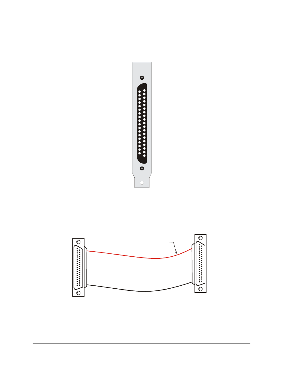
Cabling
20
1
37
19
20
1
37
19
The red stripe
identifies pin # 1
Figure 2-4. C37FF-x cable
2-5