Signal connections – Measurement Computing PCI-PDISO8 User Manual
Page 7
PCI-PDISO8 User's Guide
Installing the PCI-PDISO8
7
Install the MCC DAQ software before you install your board
The driver needed to run your board is installed with the MCC DAQ software. Therefore, you need to install the
MCC DAQ software before you install your board. Refer to the Quick Start Guide for instructions on installing
the software.
Complete the following steps to install the board:
1. Turn your computer off, open it up, and insert your board into an available PCI slot.
2. Close your computer and turn it on.
When you connect the device for the first time to a computer running Windows, a
Found New Hardware
dialog opens when the operating system detects the device. If the information file for this board is not
already loaded onto your PC, you will be prompted for the disk containing this file. The MCC DAQ
software contains this file. If required, insert the Measurement Computing Data Acquisition Software CD
and click
OK
.
3. To test your installation and configure your board, run the InstaCal utility installed in the previous section.
Refer to the Quick Start Guide that came with your board for information on how to initially set up and
load InstaCal.
Signal connections
The table below lists the board connectors, applicable cables and compatible accessory boards.
Board connectors, cables, accessory equipment
I/O connector type
P2: 37-pin D connector
Compatible cable
C37FF-x, where x = length in feet
C37FFS-x, where x =5 or 10 feet
Compatible accessory products
(with the C37FFS-x and C37FF-x cables)
CIO-MINI37
SCB-37
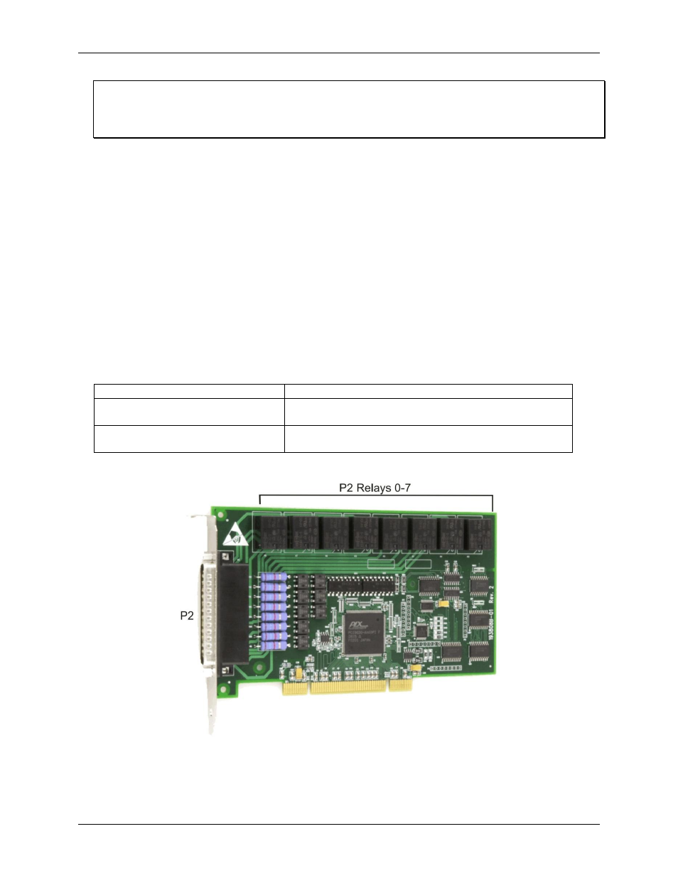
Figure 2 shows the location of the I/O connector P2 and board relays.
Figure 2. P2 connector and relays (shown with protective cover removed)
The board is shipped with a protective plate covering some components. The board in Figure 2 is shown with
the protective cover removed – we recommend that the cover always be left in place during use.