Pull-up and pull-down resistors, Replacing a fuse, Fuse specifications – Measurement Computing PCI-DIO48H User Manual
Page 14
PCI-DIO48H User's Guide
Functional Details
14
Pull-up and pull-down resistors
The PCI-DIO48H has open locations where you can install a 2.2 K , eight-resistor single inline package (SIP)
resistor network for each port. The locations are labeled
PORT 1A
,
PORT 1B
,
PORT 1C
(RN10 to RN12), and
PORT 2A
,
PORT 2B
, and
PORT 2C
(RN13 to RN15).
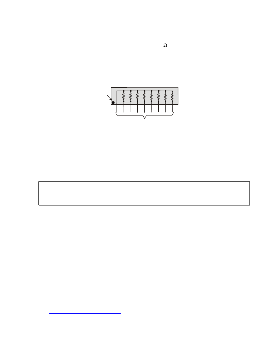
The SIP is made up of eight 2.2 K resistors. One side of each resistor is connected to a single common point and
brought out to a pin. The common line is marked with a dot or line at one end of the SIP. The remaining resistor
ends are brought out to the other eight pins (refer to Figure 4).
2.2 KOhm SIP
Dot
(LO or HI)
I/O Lines
Figure 4. Eight-resistor SIP schematic
The SIP may be installed as pull-up or pull-down. At each RN# location, there are 10 holes in a line. One end of
the line is +5V, the other end is GND. They are marked
HI
and
LO
respectively. The eight holes in the middle
are connected to the eight lines of a port.
For a pull-up function, mount the SIP with the common pin (marked with a dot or line) in the
HI
position.
For a pull-down function, mount the SIP with the common pin in the
LO
position.
When installing pull-up and pull-down resistor SIP packs, we recommend using a 2.2 K, eight-resistor SIP
(MCC part number SP-K2.29C).
Unconnected inputs float
Unconnected inputs typically float high, but not reliably. If you are using a PCI-DIO48H for input and have
unconnected inputs, ignore the data from those lines. You do not have to terminate input lines. Unconnected
lines will not affect the performance of connected lines. Mask out any unconnected bits in software.
Replacing a fuse
The PCI-DIO48H has a 1 amp slow blow fuse connected to the +5V User Output at pin 49, and is labeled
F1
on
the board. A spare fuse is installed on the board at location
F2
. Each fuse is secured to the board with clips for
convenient replacement.
A fuse will blow during operation if amperage exceeds 1 amp. If you need to replace a fuse, perform the
following procedure.
1. Pry the center of the fuse from the fuse holder clip.
2. Insert the replacement fuse into the fuse holder clip.
Fuse specifications
Refer to the information below to purchase additional fuses, (or an equivalent), if required:
Manufacturer: LittelFuse
®
Series: 452 Series - NANO
2®
Slo-Blo
®
Subminiature Surface Mount Fuse
Part number: 0452001. (Include the period as part of the item number.)
1 amp, 125 volts, 0.225 Ω