Cables, Field wiring and signal termination – Measurement Computing PCI-DAS1001 User Manual
Page 15
PCI-DAS1001 User's Manual
Installing the PCI-DAS1001
14
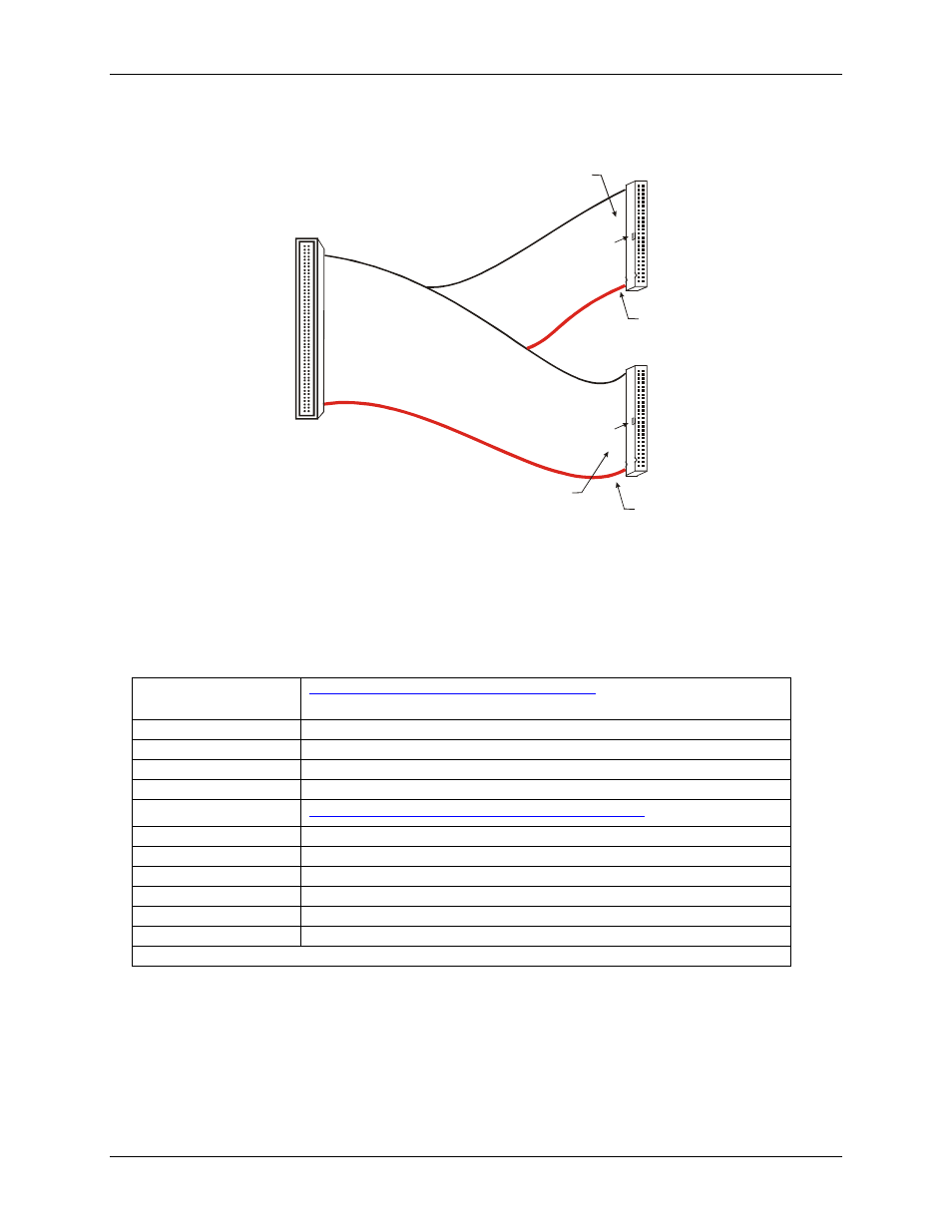
Cables
1
50
2
49
51
100
52
99
100
50
51
1
Key
Key
The red stripe
identifies pin # 1
The red stripe
identifies pin # 51
Cable is labeled
“Pins 51-100”.
Cable is labeled
“Pins 1-50”.
Figure 2. C100FF-x cable
Field wiring and signal termination
The table below lists the MCC screw terminal and signal conditioning boards that are compatible with the
PCI-DAS1000.
Screw terminal and
BNC adapters
SCB-50
50-conductor, shielded signal connection box.
CIO-MINI50
50-pin universal screw terminal accessory.
BNC-16SE
16-channel single-ended BNC connector box.
BNC-16DI
Eight-channel differential BNC connector box.
Signal conditioning
ISO-RACK16/P
16-channel isolation module mounting rack.
ISO-DA02/P
Two-channel 5B module rack.
SSR-RACK24*
24-position solid state relay rack.
SSR-RACK08*
Eight-channel solid state relay rack.
CIO-ERB24*
24-channel electromechanical relay accessory for digital I/O boards.
CIO-ERB08*
Eight-channel electromechanical relay accessory for digital I/O boards.
* These devices require the DADP-5037 PCI-DAS to 37-pin SSR and ERB adapter board.