Differential input mode, Single-ended input mode, Connecting the board for i/o operations – Measurement Computing PCI-DAS1001 User Manual
Page 12: Connectors, cables – main i/o connector
PCI-DAS1001 User's Manual
Installing the PCI-DAS1001
11
Differential input mode
When all channels are configured for differential input mode, eight analog input channels are available. In this
mode, the input signal is measured with respect to the low input. The input signal is delivered through three
wires:
The wire carrying the signal to be measured connects to CH# IN HI.
The wire carrying the reference signal connects to CH# IN LO.
The third wire, typically a system ground, connects to LLGND.
Single-ended input mode
When all channels are configured for single-ended input mode, 16 analog input channels are available. In this
mode, the input signal is referenced to the board's signal ground (LLGND). The input signal is delivered
through two wires:
The wire carrying the signal to be measured connects to CH# IN HI.
The second wire connects to LLGND.
Connecting the board for I/O operations
Connectors, cables
– main I/O connector
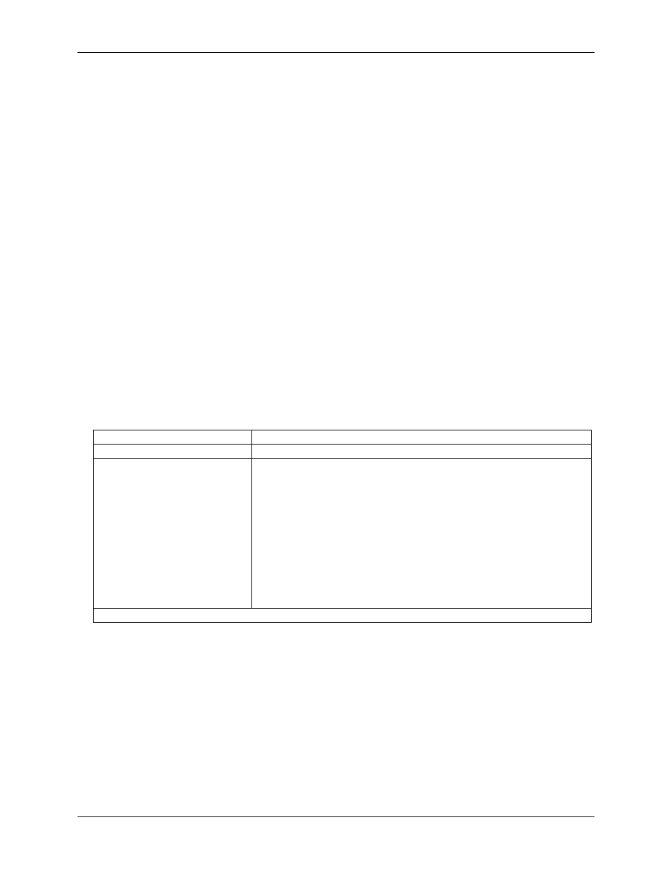
The table below lists the board connectors, applicable cables, and compatible accessory boards for the PCI-
DAS1001.
Board connectors, cables, accessory equipment
Connector type
100-pin high density Robinson Nugent connector
Compatible cable
C100FF-x, unshielded ribbon cable. x = length in feet (Figure 2)
Compatible accessory products
(with the C100FF-x cable)
ISO-RACK16/P
ISO-DA02/P
CIO-ERB08*
CIO-ERB24*
SSR-RACK08*
SSR-RACK24*
BNC-16SE
BNC-16DI
CIO-MINI50 (2 required)
CIO-TERM100 (1 required)
SCB-50 (1 required)
* These devices require the DADP-5037 PCI-DAS to 37-pin SSR and ERB adapter board.