3 register descriptions, 1 introduction – Measurement Computing PC104-PDISO8 User Manual
Page 9
3 REGISTER DESCRIPTIONS
3.1 INTRODUCTION
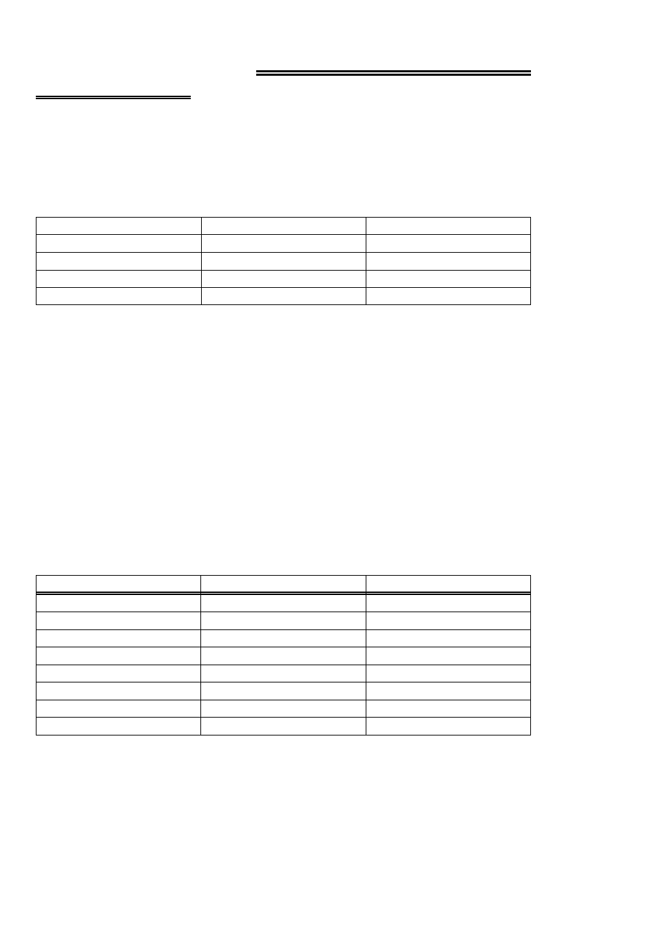
Two, eight-bit registers located at the base address (relay output) and base + 1
(isolated inputs) are read or written to for control of relays, read back the state of
relays or sense inputs (Table 3-1).
Table 3-1. Board Registers
Not Used
BASE + 3
Not Used
BASE + 2
Read Only
Isolated Inputs
BASE + 1
Relay Outputs
BASE + 0
READ/WRITE
RELAY OUTPUT
BASE ADDRESS
Although the PC104-PDISO8 decodes up to four addresses, two of those are not used.
This conforms to the design of the original PDISO-8, of which the PC104-PDISO8 is
a true clone.
Please use the Universal Library if you are programming from a high level language.
The registers are written to and read from as a single 8-bit byte. Each bit controls an
output or represents the state of an input.
Both registers are read left to right. The leftmost bit being the most significant bit.
Following this format, bit 7 of BASE + 0 corresponds to relay 7 and bit 0 to relay 0.
To construct a control word, refer to Table 3-2 for bit weights.
Table 3-2. Bit Weights
80
128
7
40
64
6
20
32
5
10
16
4
8
8
3
4
4
2
2
2
1
1
1
0
HEX VALUE
DECIMAL VALUE
BIT POSITION
Example: To assemble a control byte with relays 0, 1, 3, 5, and 7 turned ON , refer to
Table 3-3 for the coding.
5