Warning – Measurement Computing CIO-RELAY08 User Manual
Page 13
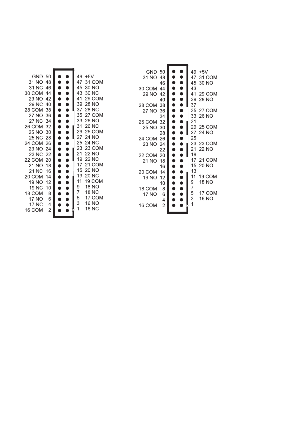
Figure
5-3.
CIO-RELAY24 & 32
Figure 5-4. CIO-RELAY24/M & 32M
Connector
Connector
The CIO-RELAY24 & 32 connector (Figure 5-3) is the center of the board.
The connector for relays 0 through 15 is closest to the computer back-plate.
The Form-A relays of the /M versions have NO and COM connections only
(Figure 5-4).
NOTE: Pins for relays 24 through 31 are open on the CIO-RELAY24 & -24/M
versions.
WARNING!
High voltages will be present on the CIO-RELAY boards when you have connected
high voltage inputs or outputs to the CIO-RELAY connector. Use extreme caution!
Never handle the CIO-RELAY board when HV signals are connected to the board.
DO NOT REMOVE THE PROTECTIVE PLATES FROM THE BOARD
.
9
This manual is related to the following products: